Welcome to Laser Pointer Forums - discuss green laser pointers, blue laser pointers, and all types of lasers

LPF Donation via Stripe | LPF Donation - Other Methods

Links below open in new window

ArcticMyst Security by Avery

Building a powerful red laser

Fiddy

0
Joined
May 22, 2011
Messages
2,726
Points
63
OK thanks, and by output I ment mW of the laser.


looking at this:

23963d1256789548-differences-similarities-red-blu-diodes-p1-8x-vs.-loc-piv-plot.jpg


@ 360mA your output will be 260mW with a 405-G-1 lens.

If you use a AR Coated Acrylic lens or Aixiz glass they are around 15% less than the 405-G-1 lens.

So 260 x 0.15 = 39

therefore 260 - 39 = 221mW

So around 221mW with a decent lens.

Now I'm from Israel so it's kinda hard to keep it up with:

What is a test load? If I'll just connect the driver to batterys with out a diode, shoulden't I know the mA? and in what stage to I solder the diode to the driver? please explain slowly :)

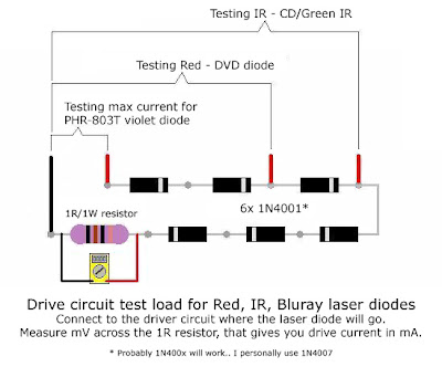
A test load is used to determine the current output of the driver BEFORE soldering to your laser diode.

IF you connect the driver to batterys without a diode, the driver will destroy itself. The driver NEEDS a load to work properly.

how did you plan on measuring the current without a load?

and in what stage to I solder the diode to the driver? please explain slowly :)

  1. get a test load
  2. Solder driver to test load
  3. Attach power source to driver
  4. measure the current in your driver.
  5. Set the current in your driver say 350mA? read here.
  6. Disconnect power source from driver.
  7. De-solder driver from test load.
  8. Short out driver output wires.
  9. Solder LD to driver.
  10. Install in host
  11. Start lasing.


Joined
Aug 15, 2011
Messages
311
Points
0
Wow thanks, but one thing:
I have a 20X DVD burner diode, not 8.

and I need to get somthings clear:
1. Where do I get a test load?
2. How do you DESOLDER?
3. why should I short the output wires?
4. What is an LD? mabye the diode?
5. before I put it in a host I just want to check that everything works fine, will it work without a host first? what host do you reccomand?

Thank you so much!
 

Fiddy

0
Joined
May 22, 2011
Messages
2,726
Points
63
LOC = LPC-815 = 20x

1.Build a test load:

test+load02.jpg


2. heat up and pull the things away to desolder?

3. you must short the driver outputs together before soldering to discharge the drivers capacitor so it doesn't discharge into the laser diode and kill it the first time you turn it on.

4. LD = laser diode.

5. yes it will work fine without a host, there are heaps of hosts available take your pick! A Aurora C6 is a decent one.
 

Fiddy

0
Joined
May 22, 2011
Messages
2,726
Points
63
I have this diode:
HighTechDealZ - 650nm 20x DVD Burner LPC815 Laser in Aixiz Module
and about 3:
What do you mean shorten the output? do you have an image?

Yes you have a diode tha burns at a disc speed of 20x when it was in the dvd burner = its model number is LPC-815 = its physical appearance is LOC (Long Open Can) all the same thing as the red line on that graph.

Where did i say shorten the output? that doesn't make any sense.....
if you mean short the output (short circuit), you touch the output positive and negative wires together to 'short out' the capacitor in the driver.
 
Last edited:

Fiddy

0
Joined
May 22, 2011
Messages
2,726
Points
63
A RKCSTR driver, it is VERY simple.

the Positive and Negative wires that you would solder onto the Laser Diode, touch them together for 5 seconds to discharge the capacitor on the driver.

Doesn't get simpler than that.
 
Joined
Aug 15, 2011
Messages
311
Points
0
LOL
I still don't get it.
When I solder, I solder the diode it self (+ and - pins) to the LD+ and LD- of the driver..
the only wires I use are the switch's, and for the batterys connecting to the driver.
 

Fiddy

0
Joined
May 22, 2011
Messages
2,726
Points
63
If you cant follow that basic instruction,
You need to read up on a lot of information that is readily available on this forum.

Good hunting.
 

Fiddy

0
Joined
May 22, 2011
Messages
2,726
Points
63
he doesnt use a test load to measure the current....you keep asking the same questions over again.

You know what, just copy what he does in the video.

if you havent killed you diode already then it should be alright to do.
 
Joined
Jun 7, 2009
Messages
118
Points
0
Do I have to short thease? In the video he doesn't

In video, styroPyro already has laser diode working.

Video does not show laser being tested before working.

Your driver should plug into test load first (before), to see what current will be.

But after you do this, driver will still have charge inside it.

If you plug driver into laser, without getting rid of old charge/current inside, will hurt your diode!

To get rid of old charge/current is why you short the connection.

You must short the + and - wires (put them together) to make sure, any energy left inside driver, from testing, does not jump into laser when you connect.
 
Last edited:
Joined
Aug 15, 2011
Messages
311
Points
0
Wow! That really helped me! You explained everything to me!
Thank you!! :D
ONLY one question:
if ill put them together, then I won't be able to connect batterys and also, how do I put them together?
 
Joined
Aug 14, 2011
Messages
1,109
Points
0
I'm scared for the safety of innocent bystanders if this guy ever gets a laser put together... :whistle:

For real dude. Read a bit. You'll learn heaps.
 
Joined
Aug 15, 2011
Messages
311
Points
0
hahahaha lol
It's kinda hard to read for me so much info in English so I settle for videos, and you guys! :)
 

yzer

0
Joined
May 10, 2011
Messages
85
Points
0
ChukiDori's advice in post #44 is excellent. Be sure to short the output of the driver after you adjust it and before soldering the laser diode to the driver. If you don't, current left in the driver capacitor will kill your laser diode as soon as you touch the diode pins to the driver output.

The G-1 lens is excellent for burning. However, I recommend trying an Aixiz AR coated 3-element glass lens first. They cost less than $8 and perform very well if you want a well collimated beam. I use the same diode as you and the spot from my laser using the Aixiz glass is round and about a foot wide at 250 meters.

You can use test leads to connect your battery to the driver input, the test load to the driver output and the DMM to the test load. Test leads are simple short lengths of wire with small alligator clips on the ends.

Fiddy's test load diagram in post #35 is excellent. After you solder the test load together the diode end of the test load connects to the Micro-Drive driver output + and the resistor end connects to the driver output -.

You can connect the DMM to the test load using test leads. DMM test probes connect across the test load resistor, or to either end of the resistor. I like to have the DMM connected and running throughout the adjustment because current coming from the driver will be highest right after power is turned on and will fall off slightly a few seconds later.

Personally, I don't advise running the LPC-815 laser diodes much past 360mA. I killed diodes trying to run them close to 390-400mA. They won't be that much brighter at 400mA then they are at 360mA.


Top