Welcome to Laser Pointer Forums - discuss green laser pointers, blue laser pointers, and all types of lasers

Buy Site Supporter Role (remove some ads) | LPF Donations

Links below open in new window

FrozenGate by Avery

Building a "everycolor" / RGB >3W Laserpointer

It will take a while.
I am in the middle of a move.
So i don't have much free time.
However i do have News:

I am in the middle of programming the PWM stuff for dimming.
The uC will generate a high frequency PWM that gets smoothed to a variable analog voltage that feeds the laserdrivers.
This will give me a constant power laser output.
However i like the idea of generating rainbow lines with this pointer.
For example: One mode of the pointer will be a rainbow mode.
This will be completely different than the Sanwu pointer "colorchange mode"
This mode will adjust the brightness of each laser color very rapidly. This will give the illusion of a white beam that does not change color.
However if the pointer gets moved it will draw a rainbow colored line.
This stuff needs high speed programming and electronics.
The good news: It already works a little.
I did already implement the menu system and the PWM output.
BUT the menu systems still needs work. Right know its to complicated.

If someone is interested:
I do have 20 driver PCBs, so i could sell one or two.
Software is still pre-alpha but this will change.
Don't hesitate to write a PM.


TODO:
- Programming new menus system
- Optimizing speed of pwm generation
- Optimizing battery percentage readout (the ADC values are all over the place, maybe a programming/electrical problem)
- completing CAD design of the back housing
- completing CAD design of the battery holder
- CAD design of the back cap with key switch

I will post if i get something done!

have a nice day

If you need any CAD assistance / design help, I will gladly help! :)
Btw.. Witch processor you will use? I have full load of different PWM color modes / cycles for PIC processors written in assembly some where at my computer..


Hello!

Thanks for your offer, greatly appreciated!
However my CAD skills are good and i am able to 3d Print a prototype before machining it in metal.
So i will do this part on my own.

I am using a AtTiny1616 as a processor. My programming skills are not that good, so i am using Arduino to write software for it.
I don't use basic digitalread() (direct port manipulation instead) but i don't program in assembler either :D.
So i don't think the color changing assembler code will help me.
 
Sorry, no updates :(
However the project is not dead. Its the first item of my todo list.

My new apartment is nearly done, so not long.
 
Hello!

I did get something done, however the project is not finished.

The programming is stuck.
I did program the pcb to do everything i wanted, RGB fades, R,G,B adjust with the encoder, EEPROM.
But i don't like it. The userinterface does not seem right.
Right know i do the following:

turn on -> RGB led shows Battery status (Green->Red)
one click switches to the next Mode.
The encoder lights up red, turning the encoder will adjust the brightness of the red laser.
Next click gets me to the green laser brightness.
Next click gets me to the blue laser brightness.
Next press activates the RGB color fade mode. Rotating the encoder will change the fade speed.
Next press activates the RGBYMC color cycle mode. Rotating the encoder will change the cycle speed.
Next press gets the pointer back to the initial state.
The whole time the laser is off.
To activate the laser i implemented a long press. Pressing the encoder for 2s will switch the laser on, releasing the button will turn it off again. This can be done anywhere in the menu. Rotating still works for changing color/speed while the button is pressed.

There is also a way to activate a continuous laser on mode. This is done with double clicking the encoder. This turns the laser on continuous. double clicking again will switch it off. While the laser is continuously on, the menu can still be navigated.

I did also implement crude logarithmic dimming to get a better response from the laser diodes. There is also threshold adjust, however only in software.

But its not as easy to use as i would like.
for example: If i want a yellow beam i need to do:
Switch on -> press the encoder to get to red adjust -> turn red up -> press again to get to green adjust -> turn green up -> double clicking to make it tase continuously.
Nice, however if i didn't turn up red enough or if i want to adjust it again i need to:
click again to get to blue -> click again to get to rgb mode. (this will change the color of the laser to rgb fade) -> click again until i get to red adjust again. Getting to red adjust will reload the values that were adjusted before, now i can turn red up a notch.
This seems like a hassle and is also bad because i get the wrong color in-between.

Does anyone have any suggestion how to make the menu more practical?

It seems like i need at least another button, this would make a "LaserOn" button. Disconnecting the encoder from turning the laser on would make getting "back" in the menu easier because i could use a long or a double press.
However i don't like another button
 
Last edited:
Hello Guys!

I do have something to show.
I did make a video to showcase the pointerhead, its still not finished.


Todo:
- complete case
- implement temperature protection
- maybe change the userinterface
- change speed setting for rgb Fade and rgb Flash (its the wrong way around)


The driver is working as expected and i do have some left.
If somebody wants one, please write a PM.
 
Very nice project.
I am curious how you implemented the PWM variable brightness function. You say you are using filtered pwm to get an adjustable analog voltage, but how is that voltage controller the LD current. What buck IC are you using?

For PWM are you using the normal 490Hz or 980Hz or a higher pwm frequency? I looked at the possibility but to get a stable analog voltage the filtering time constant has to be a bit too high at normal pwm frequency.
 
Last edited:
Hello Guys,

I did finish the CAD case drawings.
I would have liked to install a key switch to prevent unauthorized access. However space is tight and I wanted high quality, so I did choose a combined interlock (key) and programming port. It consists of a rectangular 4pin connector.
Two pins are used for interlock, there will be a "key" (plug) that bridges two pins to get the laser running. The other two pins will be for programming without opening the laser.
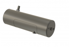
Case.png
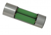
Batterie are 2x 18650 next to each other.
case_open.png


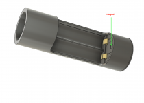
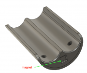
Battery cover will be magnetically fixed.
case_without_batterys.png

battery_cover.png
Material for the outer shell will be aluminum, the inner parts like the battery holder are 3D printed.
Overall length is 185mm or 7,28", outer handle diameter is 42mm or 1,65", head diameter is just under 50mm or 2" (could be smaller at the cost of duty cycle)
Impressively small for a fully corrected 3,3W RGB pointer.

Keep you updated
 
Hello Guys!

I do have something to show.
I did make a video to showcase the pointerhead, its still not finished.


Todo:
- complete case
- implement temperature protection
- maybe change the userinterface
- change speed setting for rgb Fade and rgb Flash (its the wrong way around)


The driver is working as expected and i do have some left.
If somebody wants one, please write a PM.
Will you show a video of full 3.3w power, and also various shades of white with slight colors added? I would love to see it
 
Will you show a video of full 3.3w power, and also various shades of white with slight colors added? I would love to see it
I will post something better when its done. Not a shaky phone video with bad framing...

There is still a lot of work in there.
Currently i am waiting on the battery contacts and i still need to order the magnets.
After that i need to print the battery holder in SLA, FMD does not seem good enough for the battery contacts.
However i don't own a SLA printer, so i am looking for one or someone that can print for me. (Only locally)
That will also take some prototypes to get it just right.

So don´t expect anything too soon.
But don´t be sad either: i will post something as soon as i have it.
 
UPDATE:

I did buy another 3D printer, a resin one. I couldn't find someone who would lend me one and the battery compartment needs high precision. Thats a good enough excuse for me to buy a cheap printer :D

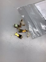
I did get the battery contacts:
image3.jpeg

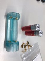
Next step: testing the fit

image4.jpeg

Nice, worked first try!

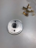
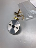
Making the back plate with combined Interlock and programming header:
image7.jpegimage8.jpeg

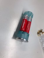
Everything assembled:
image2.jpeg

Looks really nice, the battery fit nicely. These are very cheap ones. These are not sufficient for powering the pointer! I need around 4A and the cheap Chinese batterys can not deliver that.

TODO:
- Making the case and battery door in metal
- make a case for the pointer
 
UPDATE:

I did buy another 3D printer, a resin one. I couldn't find someone who would lend me one and the battery compartment needs high precision. Thats a good enough excuse for me to buy a cheap printer :D

I did get the battery contacts:
View attachment 72088

Next step: testing the fit

View attachment 72091

Nice, worked first try!

Making the back plate with combined Interlock and programming header:
View attachment 72089View attachment 72090

Everything assembled:
View attachment 72087

Looks really nice, the battery fit nicely. These are very cheap ones. These are not sufficient for powering the pointer! I need around 4A and the cheap Chinese batterys can not deliver that.

TODO:
- Making the case and battery door in metal
- make a case for the pointer
Keep the updates coming, can't wait to see the first test fire


Back
Top