

gillza
0
- Joined
- Jul 26, 2010
- Messages
- 583
- Points
- 28
Hello,
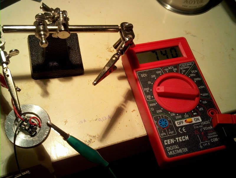
I’d like to share with you my recent build. I was trying to reach/pass the 1W mark with this laser. I got very close but not quite") . It reads at 980mW.
. It reads at 980mW.
Formalities out of the way: I do own several pairs of protective goggles for all the wavelengths that I “play” with.
Materials:
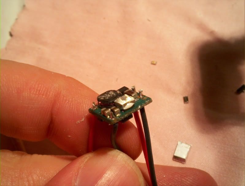
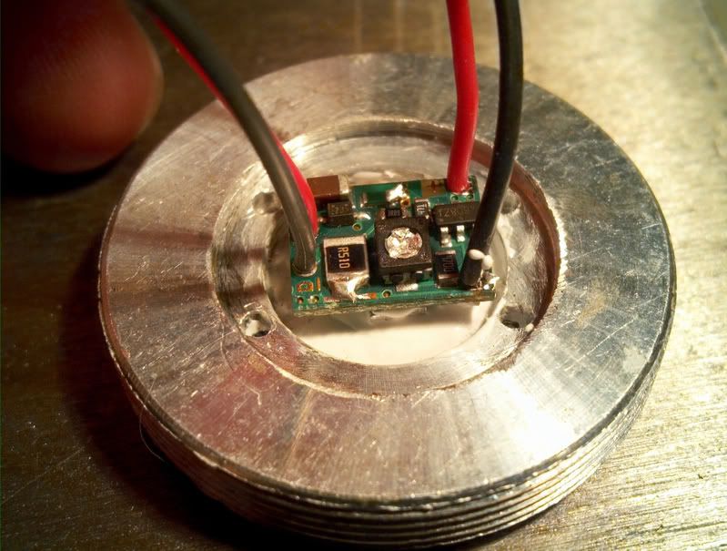
Driver: I have used my last microboost purchased over 2 years ago.
Diode: 405nm BDR-S06J 12x (from DTR)
Module: 5.6mm Copper diode module and aluminum driver housing (from DTR)
Lens: 405-G-2 (from DTR)
Lens holder: Extended lens holder (from DTR)
Host: SAIK-SA305
Heatsink: Eudaimonium's creation
Test load: 3A capable test load (from Jufran88)
Thermal compounds: Arctic Silver (for the module, capacitive)/ Arctic Alumina Epoxy (for the driver, non conductive/capacitive)
I usually like to purchase all of the components separately and put everything together by myself. I did my research and confirmed that. unless I buy everything in bulk the price for a 405nm combo kit from DTR that he sells for $96 would be pretty much the same if I’d buy parts from my several preferred sources separately. Actually the difference was 83 cents in favor of the combo kit. So I decided to try the kit.
I have requested the kit to come with the extended lens holder instead of the one in the picture and DTR offered to swap it at no extra price! There was a little harmless hiccup when the kit has arrived. It came with the original lens holder instead of the extended, and the great seller that DTR he sent me the replacement part for free. He wouldn’t even let me pay half the price or shipping expenses. Great person and sidereal customer service!
Diode Testing.
The first thing I did was test the diode on my bench PSU (HY-1803DL). With the PSU off the voltage regulator was turned almost all the way to maximum while keeping the current regulator at 0. Before connecting the leads I have shorted them to get rid of any residual charge. The module with the diode is secured in the heatsink with arctic silver added to fill in any gaps.
Very slowly the current knob was turned to 760mA (and by slowly I mean less than a degree at a time). 760mA was the current that I was hoping to drive the diode at. While changing the current I was monitoring the defocused diode output to see if I can visually detect any change in intensity ones I hit above 500mA. LPM would be a great help here. I turned of and turned on the diode with these settings to see if it will handle the startup at 760mA several times too.
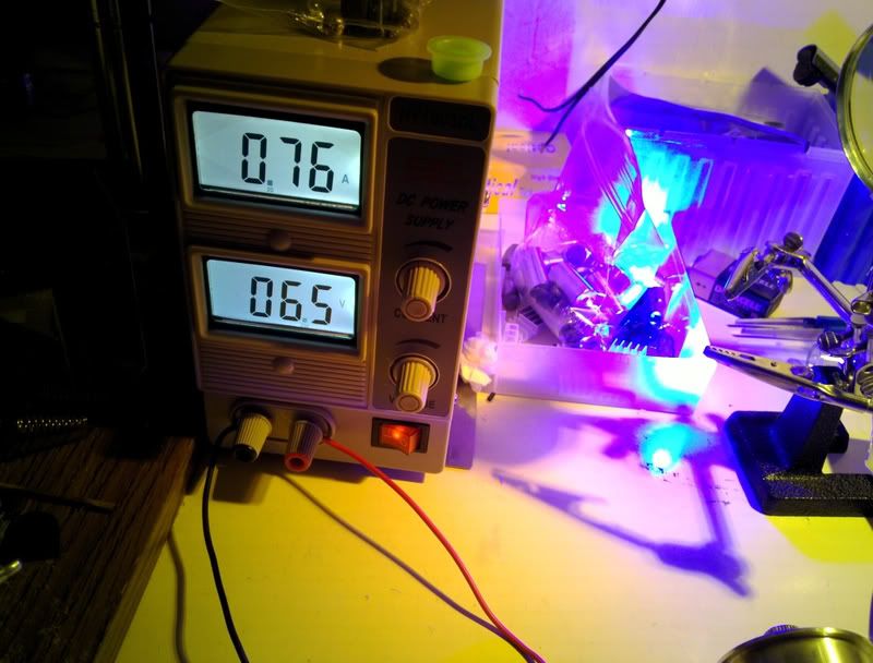
Driver Current Setting
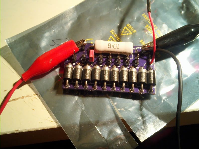
So at 760mA the diode was dropping 6.5V. The test load that I have using 1N5404 rectifier diodes which at this current according to the spec sheet should be dropping 0.8V
http://www.datasheetcatalog.org/datasheet/WINGS/1N5406.pdf
I have confirmed this by pushing 0.76A through a single diode and monitoring the drop in voltage. Spot on
So to achieve 6.5V drop with the load I will follow the equation to findout how many I will need to jumper:
6.5=0.8*X + 0.76 where 0.76 is the drop across the resistor that you are measuring. A lot of people don’t take this into account when setting the current. At high currents this drop is high enough to impact your driver’s operation. So..
X ~ 7 I will need to jumper 7 diodes to achieve a load similar to what the driver will have to provide.
After making the necessary bridges on the driver and testing it at this load, I have noticed following::
1) I can not adjust it to output 760mA. It jumps from 748mA straight up to 790mA. In addition if I leave the pot at 747mA, when on the driver momentarily jumps to 790mA anyway. So I set the current on 745mA and tested it several times at different temperatures and changing the load slightly. It seemed pretty stable.
2) At 745mA the driver overheats. The IC gets very hot to the touch and after a few seconds the current starts dropping. It needs heatsinking.
So I broke apart CPU heatsink, cut off a little piece of aluminum and glued it to the IC using Arctic Alumina thermal epoxy.
In addition the driver is glued to the slightly modified host pill for additional heatsinking.
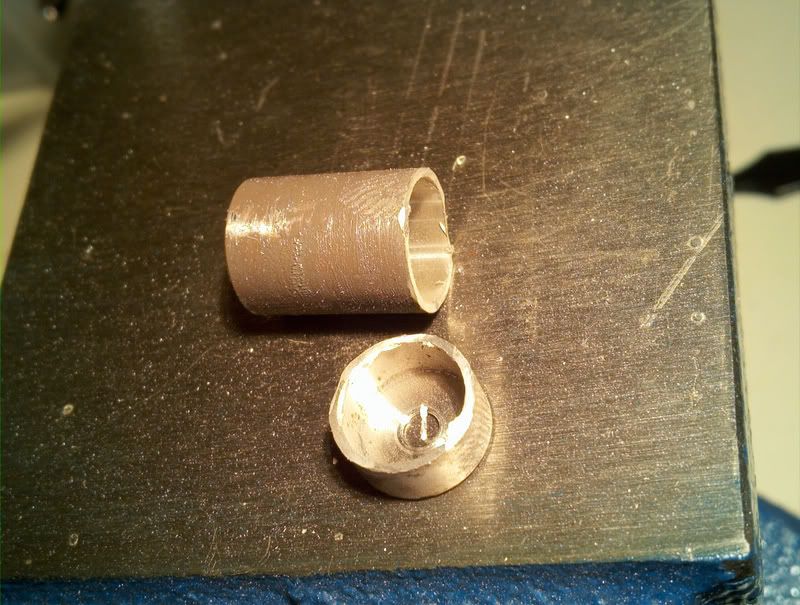
The Pill and Heatsink
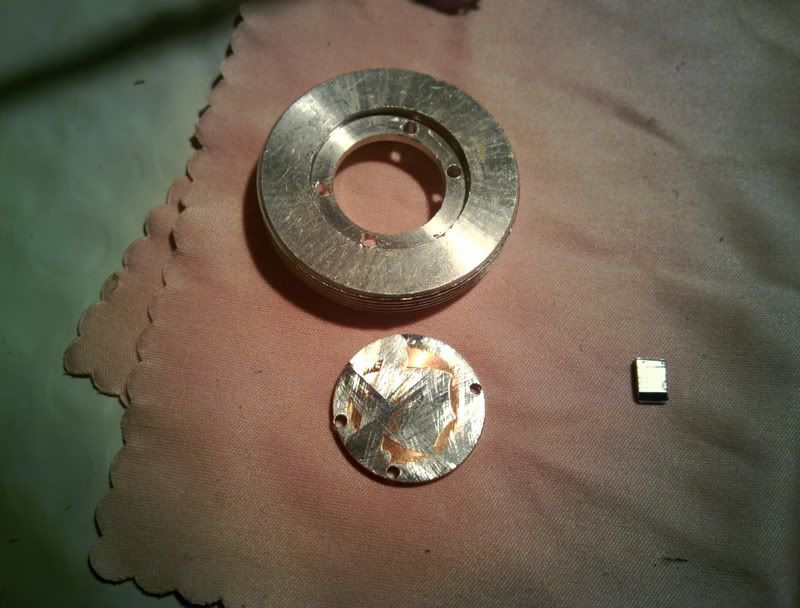
The heatsink was purchased from Eudaimonium. The transaction was flawless and he was very quick to reply answering all of the questions I had. The dude is great! When the heatsink has arrived (sooner than I thought considering it was coming from across the ocean) it looked better than I expected. Very clean! No bumps or scratches! The module shaft looked very smooth and will provide great contact with the module for improved heatsinking. Oh and did I mention? It is HUGE! Great job Eudaimonium!
The way the heatsink is machined it is assumed that you will not be using it with the host’s pill. With a regular SAIK SA-305 you will not be able to insert the heatsink all the way with the pill still in as it will protrude 1mm or so. So you are to mount your driver into the heatsink or onto it. The heatsink has a 17mm cavity which fits perfectly for round drivers wich have the battery contact on the bottom such as Blitzbuck or FMT drive and similar.
In my case however I somehow got a skinny pill. And it actually allowed leaving it inside the host.
The one on the right is the standard size pill:

So if you want to use both you can either fill off 1-2 mm from the heatsink (there is more than enough metal there) or 1mm from the top of the pill and it will work. Or you can contact Eudaimonium directly and discuss with him the options. Oh yeah one more thing when you submit a sketch of changes you want to make don’t use MS paint and mouse. Use paper, ruler, pencil and eraser Good sketch helps avoid future problems and save time.
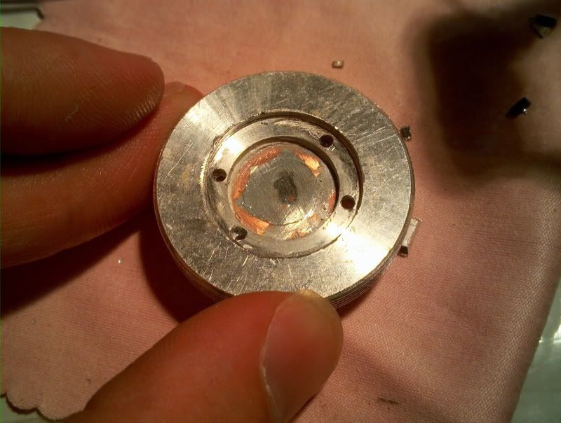
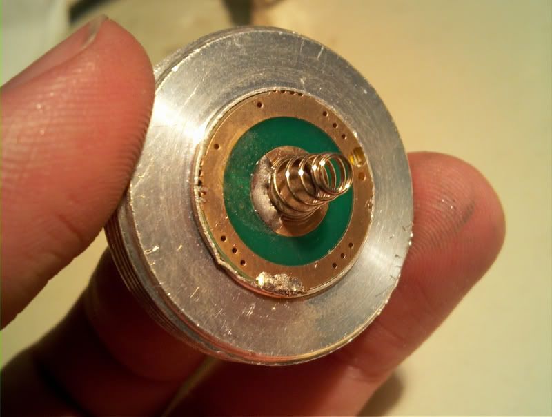
Below is the pill and a filed and drilled penny on top of which I will glue the driver.
Glued the penny in. Top of the pill
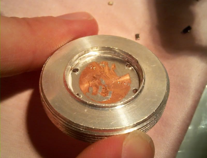
Bottom. This is where I will insert the original driver to function as contact board.
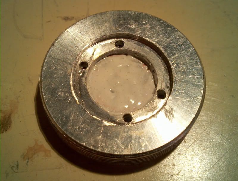
Here I have applied a thin layer of Thermal epoxy in order to create a nonconductive layer and prevent anything from shorting. Let it dry for 5min.
Fresh mix is then applied to the surfaces of the driver that will be in contact with the pill and the driver is glued onto the pill:
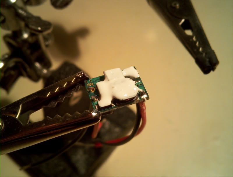
Next I removed all of the components from the original driver and soldered the battery leads from microboost on top of the board.
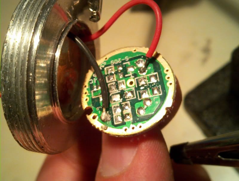
And here I made a mistake. The + wire should be soldered onto the hole that is almost in the center of the board. Or I would have to make a jumper from it to the place I soldered it to originally. Ones the error was corrected. I have applied the strips of electrical tape across the contacts to prevent any possible shorts.
Now here is the completed pill:
Sanity check:
The drier is running for about 5 minutes here. The pill got rather hot and the current dropped from 745mA to 740-738mA
Onto the heatsink:
I have decided to cut off a portion of the driver compartment from the module because otherwise the wires from the driver to the diode would not fit anywhere.
I could have completely removed the driver holder compartment but … what’s left of it was screwed back onto the module.
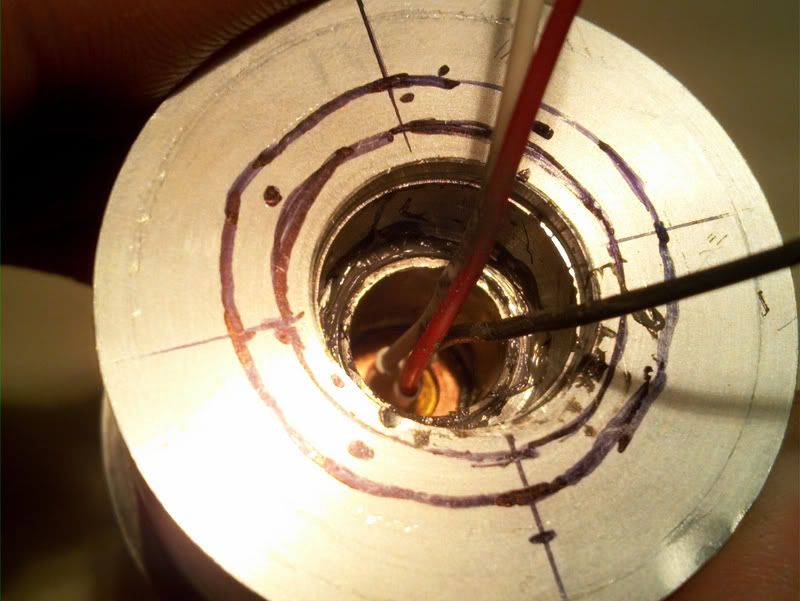
Those black lines is me figuring out what how I want to modify the heatsink for my next build. Ignore them.
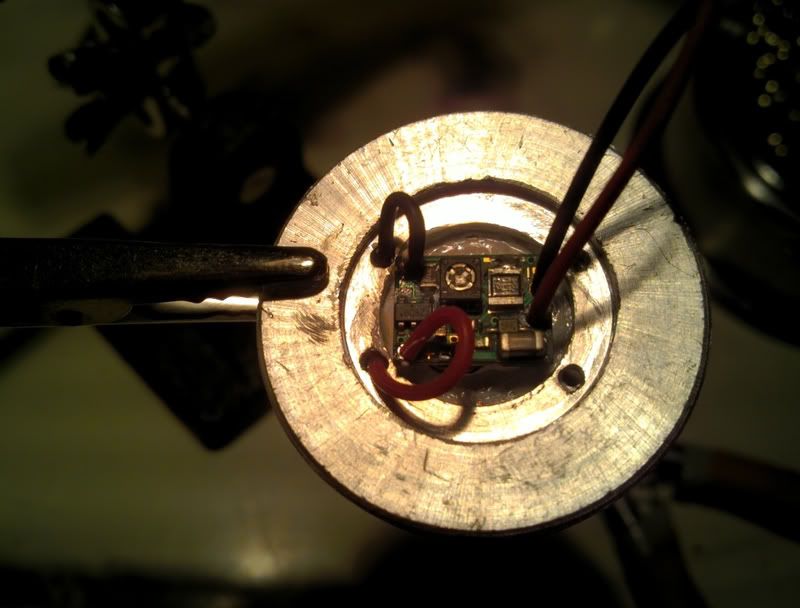
The heatsink is inserted into the head and the leads are connected to the driver. This will bitme me in the ass in the future when I will need to remove the head for whatever adjustments to the setup or so. The wires need to be as short as possible in order to be folded and fitted inside the heatsink cavity without twisting madly or damaging the driver itself or diode leads. So make them short and use some kind of tiny wire connectors instead of permanently soldering them I guess.
The white wire is from the case pin. I cut it off even shorter and liquid taped the end so that it would not short anything.
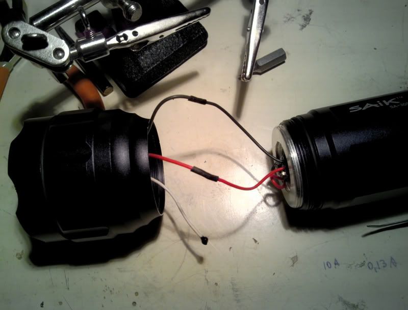
After the wires are packed in the cavity I have screwed the head with the heatsink on and MADE SURE that the heatsink is not rotating with the head. Kept is stationary with a finger. Otherwise the wires will twist too much.
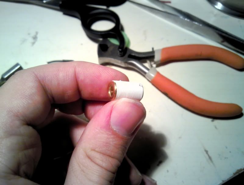
Oh I also like to teflon the lens holder and take the spring out:
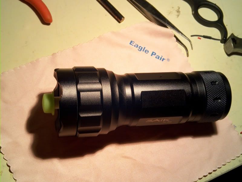
All done!
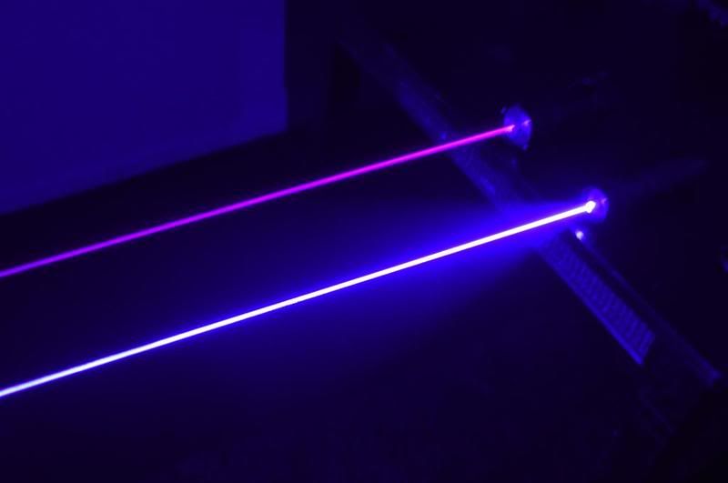
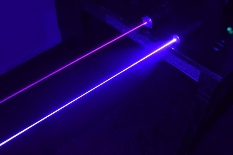
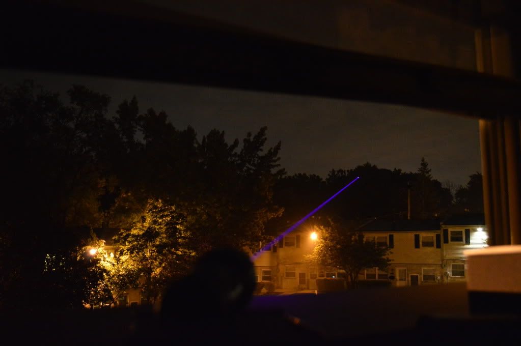
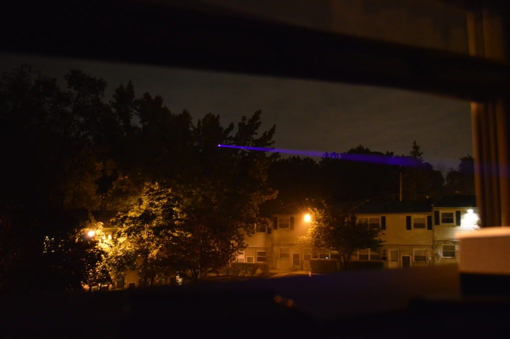
Beamshots:
No smoke/ shitty n900 camera:
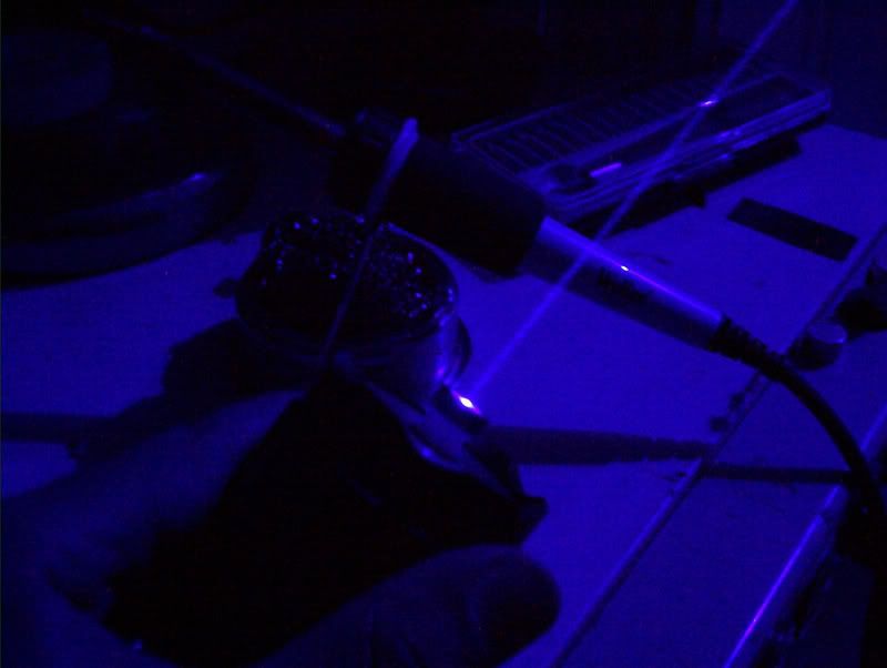
A bit of smoke/ still shitty camera:
A bit of smoke better camera/shitty cameraman:
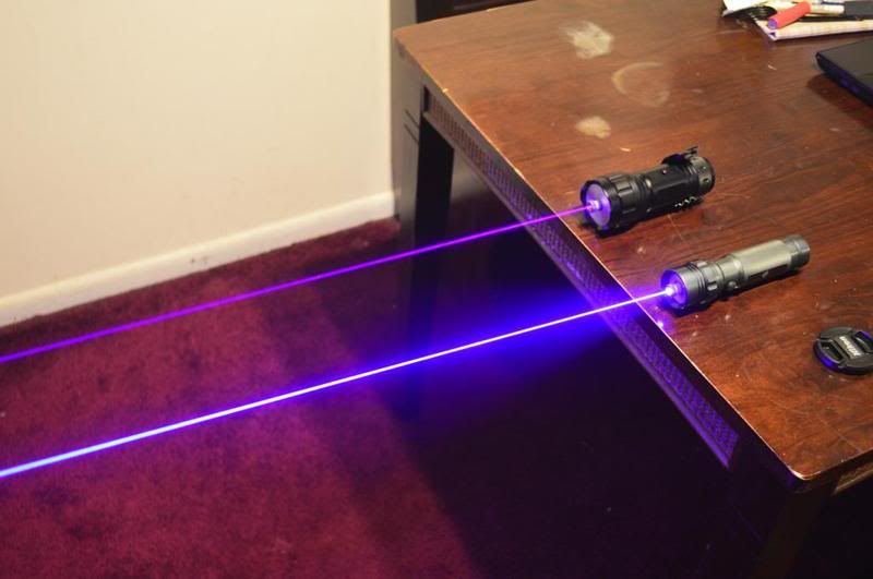
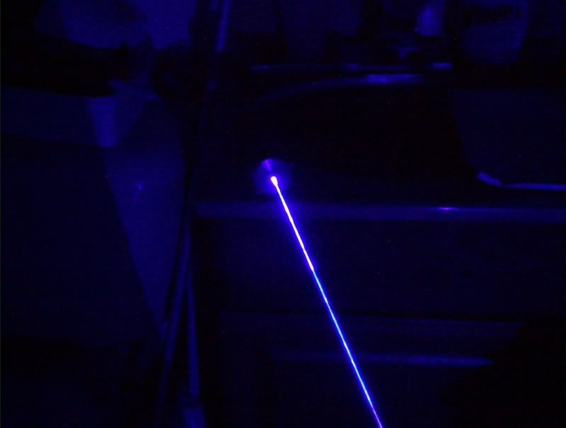
My guidesman 445nm laser is used for comparison. The lens was dirty, so you can see the splash...
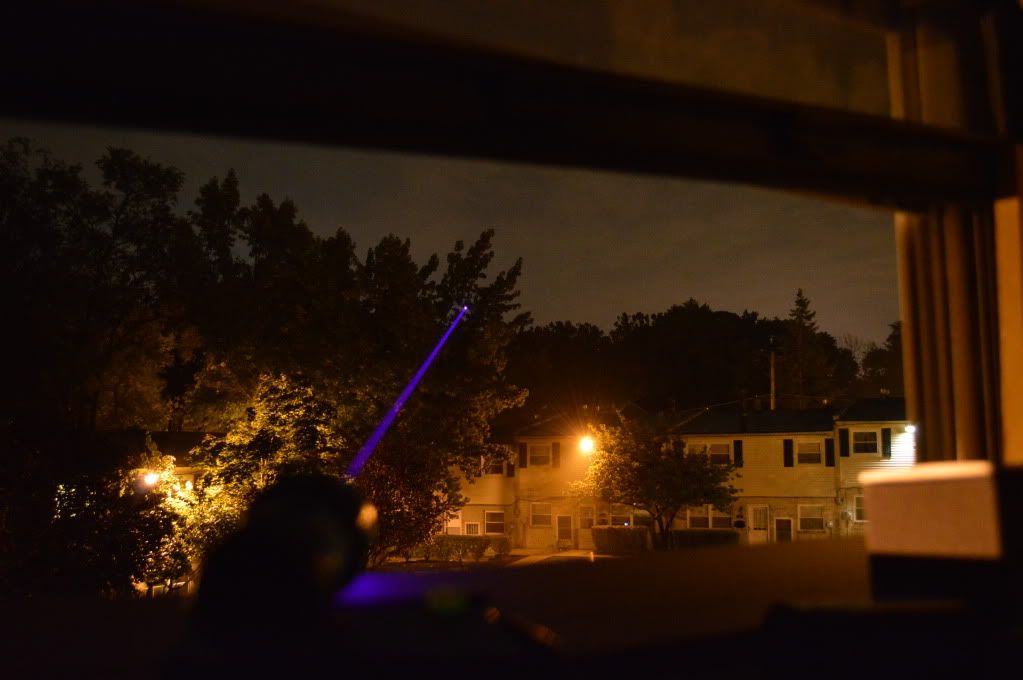
And some more:
LPM measurement:
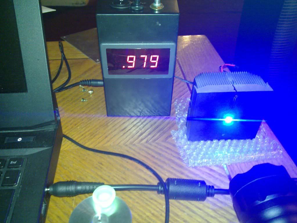
So not quite 1W but veeery close. Next one perhaps
Appendix
The first time I had to replace the stock lens for my 445nm build I found a simple way of doing it without ever touching the lens with tweezers or fingers.
For those who are interested and are buying the lens separately here is how I do it:
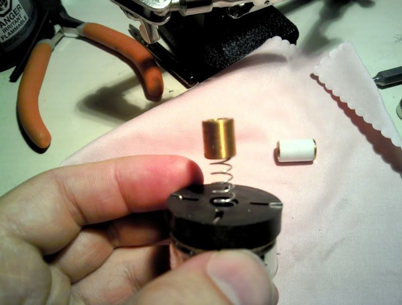
You will need a flat screwdriver tip that fits inside the lens holder (I don’t remember the number of the tip and will look it up later). Insert the tip inside the holder and unscrew the insert like so:
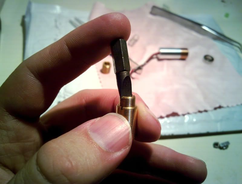
Than I am going to use head from Guidesman flashlight as a lens support when I take it out. Any spring of appropriate size will do, or any tube. The reason I used the spring ws because it supports the convex side of the lens nicely:
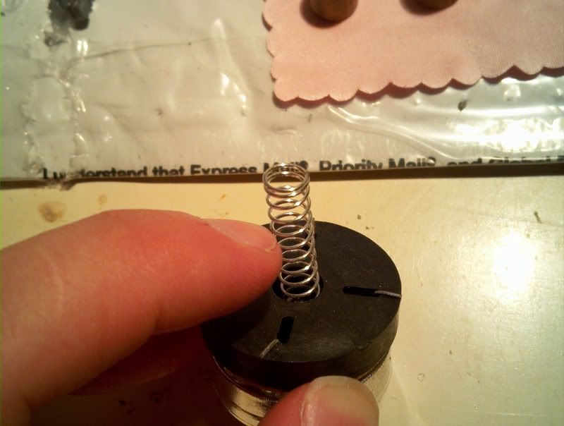
Insert the spring end into the holder. Flip the holder with the spring downside up.
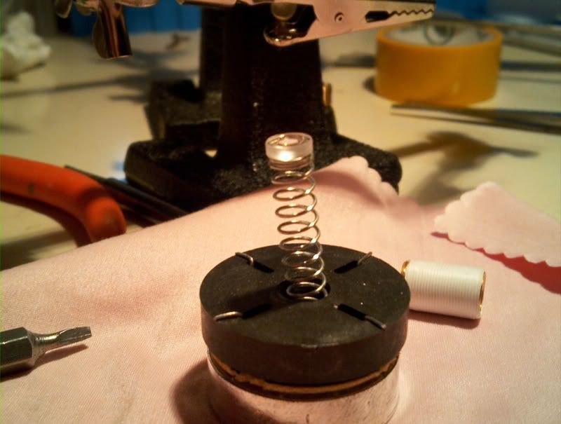
Slowly lift the lens holder up. You will end up with this:
Now do everything in reverse order using the extended holder and you are done.
I’d like to share with you my recent build. I was trying to reach/pass the 1W mark with this laser. I got very close but not quite
. It reads at 980mW. Formalities out of the way: I do own several pairs of protective goggles for all the wavelengths that I “play” with.
Materials:
Driver: I have used my last microboost purchased over 2 years ago.
Diode: 405nm BDR-S06J 12x (from DTR)
Module: 5.6mm Copper diode module and aluminum driver housing (from DTR)
Lens: 405-G-2 (from DTR)
Lens holder: Extended lens holder (from DTR)
Host: SAIK-SA305
Heatsink: Eudaimonium's creation
Test load: 3A capable test load (from Jufran88)
Thermal compounds: Arctic Silver (for the module, capacitive)/ Arctic Alumina Epoxy (for the driver, non conductive/capacitive)
I usually like to purchase all of the components separately and put everything together by myself. I did my research and confirmed that. unless I buy everything in bulk the price for a 405nm combo kit from DTR that he sells for $96 would be pretty much the same if I’d buy parts from my several preferred sources separately. Actually the difference was 83 cents in favor of the combo kit. So I decided to try the kit.
I have requested the kit to come with the extended lens holder instead of the one in the picture and DTR offered to swap it at no extra price! There was a little harmless hiccup when the kit has arrived. It came with the original lens holder instead of the extended, and the great seller that DTR he sent me the replacement part for free. He wouldn’t even let me pay half the price or shipping expenses. Great person and sidereal customer service!
Diode Testing.
The first thing I did was test the diode on my bench PSU (HY-1803DL). With the PSU off the voltage regulator was turned almost all the way to maximum while keeping the current regulator at 0. Before connecting the leads I have shorted them to get rid of any residual charge. The module with the diode is secured in the heatsink with arctic silver added to fill in any gaps.
Very slowly the current knob was turned to 760mA (and by slowly I mean less than a degree at a time). 760mA was the current that I was hoping to drive the diode at. While changing the current I was monitoring the defocused diode output to see if I can visually detect any change in intensity ones I hit above 500mA. LPM would be a great help here. I turned of and turned on the diode with these settings to see if it will handle the startup at 760mA several times too.
Driver Current Setting
So at 760mA the diode was dropping 6.5V. The test load that I have using 1N5404 rectifier diodes which at this current according to the spec sheet should be dropping 0.8V
http://www.datasheetcatalog.org/datasheet/WINGS/1N5406.pdf
I have confirmed this by pushing 0.76A through a single diode and monitoring the drop in voltage. Spot on
So to achieve 6.5V drop with the load I will follow the equation to findout how many I will need to jumper:
6.5=0.8*X + 0.76 where 0.76 is the drop across the resistor that you are measuring. A lot of people don’t take this into account when setting the current. At high currents this drop is high enough to impact your driver’s operation. So..
X ~ 7 I will need to jumper 7 diodes to achieve a load similar to what the driver will have to provide.
After making the necessary bridges on the driver and testing it at this load, I have noticed following::
1) I can not adjust it to output 760mA. It jumps from 748mA straight up to 790mA. In addition if I leave the pot at 747mA, when on the driver momentarily jumps to 790mA anyway. So I set the current on 745mA and tested it several times at different temperatures and changing the load slightly. It seemed pretty stable.
2) At 745mA the driver overheats. The IC gets very hot to the touch and after a few seconds the current starts dropping. It needs heatsinking.
So I broke apart CPU heatsink, cut off a little piece of aluminum and glued it to the IC using Arctic Alumina thermal epoxy.
In addition the driver is glued to the slightly modified host pill for additional heatsinking.
The Pill and Heatsink
The heatsink was purchased from Eudaimonium. The transaction was flawless and he was very quick to reply answering all of the questions I had. The dude is great! When the heatsink has arrived (sooner than I thought considering it was coming from across the ocean) it looked better than I expected. Very clean! No bumps or scratches! The module shaft looked very smooth and will provide great contact with the module for improved heatsinking. Oh and did I mention? It is HUGE! Great job Eudaimonium!
The way the heatsink is machined it is assumed that you will not be using it with the host’s pill. With a regular SAIK SA-305 you will not be able to insert the heatsink all the way with the pill still in as it will protrude 1mm or so. So you are to mount your driver into the heatsink or onto it. The heatsink has a 17mm cavity which fits perfectly for round drivers wich have the battery contact on the bottom such as Blitzbuck or FMT drive and similar.
In my case however I somehow got a skinny pill. And it actually allowed leaving it inside the host.
The one on the right is the standard size pill:
So if you want to use both you can either fill off 1-2 mm from the heatsink (there is more than enough metal there) or 1mm from the top of the pill and it will work. Or you can contact Eudaimonium directly and discuss with him the options. Oh yeah one more thing when you submit a sketch of changes you want to make don’t use MS paint and mouse. Use paper, ruler, pencil and eraser
Good sketch helps avoid future problems and save time. Below is the pill and a filed and drilled penny on top of which I will glue the driver.
Glued the penny in. Top of the pill
Bottom. This is where I will insert the original driver to function as contact board.
Here I have applied a thin layer of Thermal epoxy in order to create a nonconductive layer and prevent anything from shorting. Let it dry for 5min.
Fresh mix is then applied to the surfaces of the driver that will be in contact with the pill and the driver is glued onto the pill:
Next I removed all of the components from the original driver and soldered the battery leads from microboost on top of the board.
And here I made a mistake. The + wire should be soldered onto the hole that is almost in the center of the board. Or I would have to make a jumper from it to the place I soldered it to originally. Ones the error was corrected. I have applied the strips of electrical tape across the contacts to prevent any possible shorts.
Now here is the completed pill:
Sanity check:
The drier is running for about 5 minutes here. The pill got rather hot and the current dropped from 745mA to 740-738mA
Onto the heatsink:
I have decided to cut off a portion of the driver compartment from the module because otherwise the wires from the driver to the diode would not fit anywhere.
I could have completely removed the driver holder compartment but … what’s left of it was screwed back onto the module.
Those black lines is me figuring out what how I want to modify the heatsink for my next build. Ignore them.
The heatsink is inserted into the head and the leads are connected to the driver. This will bitme me in the ass in the future when I will need to remove the head for whatever adjustments to the setup or so. The wires need to be as short as possible in order to be folded and fitted inside the heatsink cavity without twisting madly or damaging the driver itself or diode leads. So make them short and use some kind of tiny wire connectors instead of permanently soldering them I guess.
The white wire is from the case pin. I cut it off even shorter and liquid taped the end so that it would not short anything.
After the wires are packed in the cavity I have screwed the head with the heatsink on and MADE SURE that the heatsink is not rotating with the head. Kept is stationary with a finger. Otherwise the wires will twist too much.
Oh I also like to teflon the lens holder and take the spring out:
All done!
Beamshots:
No smoke/ shitty n900 camera:
A bit of smoke/ still shitty camera:
A bit of smoke better camera/shitty cameraman:
My guidesman 445nm laser is used for comparison. The lens was dirty, so you can see the splash...
And some more:
LPM measurement:
So not quite 1W but veeery close. Next one perhaps
Appendix
The first time I had to replace the stock lens for my 445nm build I found a simple way of doing it without ever touching the lens with tweezers or fingers.
For those who are interested and are buying the lens separately here is how I do it:
You will need a flat screwdriver tip that fits inside the lens holder (I don’t remember the number of the tip and will look it up later). Insert the tip inside the holder and unscrew the insert like so:
Than I am going to use head from Guidesman flashlight as a lens support when I take it out. Any spring of appropriate size will do, or any tube. The reason I used the spring ws because it supports the convex side of the lens nicely:
Insert the spring end into the holder. Flip the holder with the spring downside up.
Slowly lift the lens holder up. You will end up with this:
Now do everything in reverse order using the extended holder and you are done.
Last edited:


")