Welcome to Laser Pointer Forums - discuss green laser pointers, blue laser pointers, and all types of lasers

Buy Site Supporter Role (remove some ads) | LPF Donations

Links below open in new window

FrozenGate by Avery

Blue laser 74W NUBM35 Portabl?

@RedCowboy
I think it would be better if each row with 7 diodes has a separate power supply. Because that way I will avoid frequent battery charging and get more stable work. I will probably do a test of how it will be at 5A. That way I'll get more power at the expense of more heat. But in my case it is not a problem because this invention will be used in very short intervals of work. Probably, at 5A, a power of more than 100W will be obtained

I saw in a video that a guy used these drivers to run a 125W laser unit. I don't know if you have surveillance on them

DC 400W 15A Step-up Boost Converter Constant Current Power Supply LED Driver 8.5-50V to 10-60V Voltage Charger Step Up Module


I haven't used those drivers, I think some people have had trouble but I couldn't tell you which of the available switching type drivers are any good or not.

He needs a zoom lens on it, a centered and stationary concave then a sliding ( centered ) convex. I was able to get the same cluster size at 5 meters that you otherwise get at 30cm

You will discover that each row of 7 will focus into a bar/spot so you will see two bar clusters with space between if you use just 1 additional lens, a zoom type beam expander works better, but these arrays are not knife edged and the fast axis divergence of each beam is aggressive, so getting any work done at any real distance isn't reasonably possible without the lenses getting very wide, it's still a fun project for up close entertainment.

Always lase safely. :)
 
@RedCowboy
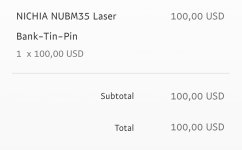
Yes, it is clear to me that the divergence will be large. For starters, I'll settle for close distances. I will experiment with different lenses in the future. Regarding the driver I showed, I have no intention of using it. I will make the one you told me. At least it's tested and works stable. I won't bother you any more about my topic. I found the NUBM35 for a pretty good price of 100$ USD. I will buy it in this case
 
When they get really cheap I thought about knife edging several of the 7 diode clusters from a few of the nubm35 arrays, but building my own corrected and knife edged array will be so much better, still if there cheap....maybe for fun.

p.s. You can test your LM338 on one of your NUBM0E lasers, put it on a heat sink and attach your resistors, then just use 2 x 18650 in series, note the LM338 will run hot so don't touch it with your fingers after it's been working.
 
Last edited:
When they get really cheap I thought about knife edging several of the 7 diode clusters from a few of the nubm35 arrays, but building my own corrected and knife edged array will be so much better, still if there cheap....maybe for fun.

p.s. You can test your LM338 on one of your NUBM0E lasers, put it on a heat sink and attach your resistors, then just use 2 x 18650 in series, note the LM338 will run hot so don't touch it with your fingers after it's been working.
Okay. Will try. That is, I only need to use 2 18650 batteries. The driver configuration remains the same 3.7A, right?

Is there a combination with the resistors to get about 4.5A?

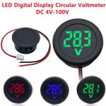
I will also install two voltmeters to see how the battery capacity is
 

Attachments

  • 1256287629-1828682042.jpg
    1256287629-1828682042.jpg
    327.8 KB · Views: 2
Last edited:
It's always the same, 1 single 1 ohm resistor will always give you 1.2 - 1.25 A and TWO 1 ohm resistors in PARALLEL result in 0.5 ohms which will result in 2.4 - 2.5A..........you see it's just basic math, 3 x 1 ohm in PARALLEL = 0.33 ohms so the constant 1.2 - 1.25 lets just call it 1.2 ok
So the constant divided by the resistance 1.2 / 1 ohm = 1.2A.........1.2 / 0.5 = 2.4A...........now if you put your 2 x 1 ohm resistors in SERIES then you would have 2 ohms and that would give you 1.2 divided by 2 = 0.6A

6 x 1 ohm in SERIES = 6 ohms and 1.2 divided by 6 = 0.2A
5 x 1 ohm in SERIES = 5 ohms and 1.2 divided by 5 = 0.24A
4 x 1 ohm in SERIES = 4 ohms and 1.2 divided by 4 = 0.3A
3 x 1 ohm in SERIES = 3 ohms and 1.2 divided by 3 = 0.4A
2 x 1 ohm in SERIES = 2 ohms and 1.2 divided by 2 = 0.6A
A single 1 ohm is 1 ohm = 1 ohm and 1.2 divided by 1 = 1.2A
2 x 1 ohm in PARALLEL = 0.5 ohms and 1.2 divided by 0.5 = 2.4A
3 x 1 ohm in PARALLEL = 0.33 ohms and 1.2 divided by 0.33 = 3.6A
4 x 1 ohm in PARALLEL = 0.25 ohms and 1.2 divided by 0.25 = 4.8A ...........or if the constant is 1.25 then 1.25 / 0.25 = 5A MAX CURRENT for the LM338, the constant of 1.2 - 1.25 is the value of the voltage drop across the zenier diode inside the regulator which is it's natural range of tolorance. So the result of 1.2A could actually be as much as 1.25A
2.4A could be 2.5A and 3.6A could be as much as 3.75A and with 4 x 1 ohm in PARALLEL you will get 4.8 - 5.0A MAX CURRENT

Now you know your NUBM0E draws about 4.5V @ 3.6-3.75A ( 3 x 1 ohm in PARALLEL ) so a single 18650 which is fully charged @ 4.2V isn't enough, so we use 2 x 18650 fully charged is 8.4V and discharged but still working is 2 x 3.5 = 7V so 2 18650 cells is the working range.

At 8V the regulator has to waste 3.5V into heat @ 3.6A ( 3 resistors ) laser diode gets 4.5V @ 3.6A and regulator wastes 3.5V @ 3.6A so that's 12.6 watts of waste heat and the LM338 is rated at 15W but can take more with a bigger heatsink and a fan, but our target is 15 or less So.......don't use more than 2 18650 in series for 1 NUBM0E.....now if you want to power 7 x NUBM0E in series you need 4.5V x 7 which is 31.5V and 9 x 4.2 is 37.8 that's fully charged before any sag under load and 9 x 3.5 is 31.5 that's discharged ....actually 9 x 3.75 is 33.75 that's your load ( 31.5 ) plus the 2 volts the LM338 needs for it's " drop out " which is in the spec sheet, now there is a low dropout model but I have been using the LM338K and know it works. So 3.75 per battery will be the discharged voltage.

Anyway fully charged our regulator and resistors have to waste 6 x 3.5A that's 21W but under load there's a little sag plus the resistors take 4.4W so the regulator on a heat sink is OK but don't use 10 cells and 8 cells aren't really enough so it's 9 cells with a working range of 4.2 to 3.75 which is reasonable charged to discharged range under load.
 
Last edited:
@RedCowboy
Thanks again for the lecture. I just work in the field of Sports and these things are completely new to me.

How much power do you think the NUBM35 will reproduce at 5A current?
 
Last edited:
I'm not an expert on anything, but I like to learn as much as I can about everything, knowledge is power and one day who knows what may be useful or needed, besides learning is fun and the tyrants can't take your knowledge.

You say that you use translator, where are you living ? I'm in Georgia, SE corner of USA
 
@RedCowboy
I live in Europe and I am from Bulgaria. In 2016, I was in the USA for a week. I have never studied English, so I use a translator. As an important rule, I write correctly in my language so that the translator can translate correctly what I want to say. 😀
 
You're doing very good with the translations.

5A is over-driving the diodes which we get away with when we over-drive the single units such as NUBM0E, but all packed in together in those arrays it's better to stay near spec, at least to start with because waste heat can bottle neck at the substrate stack, that said I have pushed mine to 5A and you notice a little difference, but waste heat also builds up faster.

Compared to a known value such as NUBM0E @ 3.5A is worth 5.5W per diode and @ 5A is worth 7.75 so 14 x 7.75 at best would be 108W and at 3.6-3.75 would be 77W so yea that adds up.......you should start with 3 resistors and evaluate, you will have more runtime to test optics as well, then overdrive when you have everything worked out, it's just a hobby and for fun so......unless you buy extra arrays @ 100.00 each probably better to start @ 3.75A ( 3 resistors )
Yes, I'll start with 3.7A and see how it goes. I currently have 5pcs NUBM0E (protected) like yours that you are using. But I will install them in the lasers I make. In Bulgaria, several people even bought one 🙂 Let's take stock with your measurement. Your device shows 7.7W at 5A with NUBM0E diode with G2 lens. My meter at 5.2A shows the same 7.7W but with a 3 Element lens. That is, for me, it can be said that the meter for $5 gives very accurate readings with a 3 Element lens, because it compensates for the difference in the inaccuracy of the meter
 

Attachments

  • Screenshot_20221203_172851.jpg
    Screenshot_20221203_172851.jpg
    829.7 KB · Views: 7
Last edited:
3 element has 30% loss, this would mean your NUBM0E is over 10W with a G2.......nope, it's just not, I have 2 of the NUBM0E and they are just like NUBM08 AND NUBM44 basically an 8W output at best when overdriven @ 5A for short duration.
 
3 element has 30% loss, this would mean your NUBM0E is over 10W with a G2.......nope, it's just not, I have 2 of the NUBM0E and they are just like NUBM08 AND NUBM44 basically an 8W output at best when overdriven @ 5A for short duration.
Yes, my point was that my meter measures fairly accurately with a 3 Element lens, which compares in power to a G2 lens on a professional meter.

Shows the same performance as a professional device with a G2 lens. In this case, I have an accurate power stop with mine using a lens 3 element, which will show very similar results on a pro unit with a G2 lens. I just have a rough idea of power. Actual power with 3 Element lens is around 5.5-6W

Otherwise my meter with G2 lens shows 9W power. That is, about 1.5W more

Pictures with Lens G2 9W - real 7.5W - 1.5w deviation
Lens G8 8W - real 7.5W - 0.5w deviation
 

Attachments

  • Screenshot_20221203_191412.jpg
    Screenshot_20221203_191412.jpg
    776.8 KB · Views: 2
Last edited:
If you are already planning to use a cordless drill body why not use the rechargeable battery as your power source and hook it up to your boost converter/regulator circuit. It would be less parts and you would only need to charge I battery
 
If you are already planning to use a cordless drill body why not use the rechargeable battery as your power source and hook it up to your boost converter/regulator circuit. It would be less parts and you would only need to charge I battery
Yes, it is, but the battery of the drill is 24V. I need about 37V. Or at least with this driver I'm going to use I need at least 37V. Otherwise, it would be a very good option, but I'm sorry in this case. It is clear that I will make something homemade from wood, plastic or from a U-shaped metal profile. I have a few ideas, but first I have to get all the components and figure out how much space I'll need.


Back
Top