Welcome to Laser Pointer Forums - discuss green laser pointers, blue laser pointers, and all types of lasers

LPF Donation via Stripe | LPF Donation - Other Methods

Links below open in new window

ArcticMyst Security by Avery

Blackbuck 6. 6 amp led or laser diode driver


Joined
Jan 29, 2014
Messages
12,031
Points
113
No one answered :(

Now I'm going to necro post too, but I need more information. The diagram I see online for the Black Buck 6 shows the use of an "optional" low current switch, but what is not given, is whether that switch operates as an open, or a closed, for current to flow to the diode. If optional, I would think an open would allow current to flow and a closure stop it so THAT switch could be left out if you didn't want to use it without a need to solder bridge the contacts. However, on all of the seller sites, all which is said is the contacts for that switch are floating. Is that to mean you don't need to use them? Probably, but I'm not sure and before thinking of that, already solder bridged them closed.

Also, for heat sinking, no mention of the preferred method of heat sinking, the chip is a LOT lower on the circuit board than the inductor and some other parts, so no way to just lay it (mechanical pressure, glue etc.) against a flat surface, or is the heat sinking contact supposed to be through the bottom? If so, there are solder pads under there which can short if placed against something conductive, no instructions, no mention.... Huh?

I thought these were the best design to come along in years due to their capabilities, but with the lack of enough information about basic functions or how to properly heat sink and with that chip down low on the board, now I'm questioning whether this design is really that great. That information is very important to have, you can't run this above 1.5 amps without proper heat sinking, so why not give more information about how to do that? It's pivotal information.

See the diagram here: https://www.ebay.com/itm/BlackBuck-...tep-Down-Buck-Laser-Diode-Driver/182591714751 - that drawing is used by all of the sellers, I'm not picking on DTR (I'm using a link to his ebay listing here to both show the diagram as well as to possibly draw others to his listings), it's what X-Wossee provided him, but I think our Russian friend who makes this driver could do better.

I'm hoping the info is out there somewhere, I've been searching this forum and through google, but not finding the info yet. I bet someone knows which thread has it, but I'm spending a lot of time and not finding it. I'm thinking I need to find a small piece of copper to put on top of that driver chip to match the height of the inductor and then glue it down to a big heat sink that way. If that is the best way to heat sink it, they should be included with each driver, probably glued to the chip too.

Another piece of information I would provide is how much the low and high end of the current adjustment pot is capable of, regardless of the max current to be about 6 amps, how much current can I accidentally over current the driver if turned too high, or is the top of the adjustment six amps?

Can someone who has used this driver please give me their perspective?


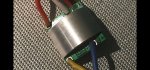
Below, is a photo of the 8 amp modulated version, it has the same problem, the chip which needs heat sinking is recessed and no mention of the best way to heat sink this on any of the seller listings. Bottom of board, top only? I know, top is best, but is there enough heat conduction to use the underside through the board? My guess is yes, it's got to be, otherwise you can't get to the pot to adjust it if mounted upside down, or a big heat sink on top, but I wish the sellers would say so. If not, this is a poor heat management design, but the electrical is outstanding otherwise, I like it. Perhaps that is what he is forced to do, if it is to remain small, just a pain to heat sink.


Chris
 
Last edited:
Joined
Mar 5, 2015
Messages
1,336
Points
113
I’ve used the 8 a few times and I’ve been told you only need to heatsink the bottom, some are using heat sink tape, I just mill out the sides of my sink so the contacts cannot make contact,

Here is one way of doing it!
 

Attachments

  • 4cJlQXW.jpg
    4cJlQXW.jpg
    105.9 KB · Views: 25
Last edited:

DTR

0
Joined
Jun 24, 2010
Messages
5,684
Points
113
Pick away. I have been meaning to add that info on flat mounting it to sink it. The board is thin and passes heat very quiet efficiently to maintain continuous duty cycle or at least the diode would get too hot before the driver would. I like to use a thin thermal tape just to give a little buffer to ensure no shorting and thermal adhesive to bond it. You don't need to sink via the top and note I said mount it to the main laser heat sink a small metal radiator will not be sufficient. Just flat mount to your main laser heastinik or if using one of the 20mm or 25mm the copper back half with driver shelf gives a spot to mount the BB6 or similar sized drivers. Same mounting style on the BB8 but it wont fit in the driver shelf's. the 25mm could have accommodated it and when I do another batch I will make them a little wider to fit it.

If you close the circuit where the diagram shows you can put a switch it actually goes off into a standby state. The BB6 will go just above 6A max. See these.


The BB8 requires the 5V ref and the Mod in to be closed for on if using a switch or bridged if not when going for always on. Open circuit/no 5V signal to the mod in is off/low power state.:beer:
 
Joined
Sep 20, 2013
Messages
17,254
Points
113
Great information as I have not had the opportunity to use one of these yet. Thanks to Jordan for the videos and the extra tips on setting one up.
 
Joined
Jan 29, 2014
Messages
12,031
Points
113
Thank Billy and Jordan,

I was hoping the heat transfer was efficient enough through the board to use the underside, my only thought on how to do so was a thin piece of adhesive heat sink tape and a way to hold the driver down, but I don't like using tape like that as it isn't as good as a thin layer of arctic silver, or their diamond stuff, but if the diode gets too hot before the driver does for most pointers, that's moot.

Perhaps if the diode is mounted in a labby with a fan that would not hold true, but for our use in pointers good enough for me. I suppose some thermal glue could work, or a thin layer of some heat sink compounds, as they are not conductive, but if you solder through those pads with wires poking through, can't do that. Careful insertion of the wires and soldering them in place so they can't poke through to the bottom would work, with a spot of fingernail polish over the solder pads on the bottom, when done, would help.

Jordan, from what you said, my understanding is my having solder bridged that contact has disabled the driver, or put it in standby mode, correct?
 
Last edited:
Joined
Jul 10, 2015
Messages
9,799
Points
113
While testing I thermally bonded my aluminum heat sink to the bottom ( underside ) of the driver, is that not OK, so far it has worked for me.

When I use the silicon pad I also used a dab of thermal mounting compound at the edges to make sure it stays put.

---EDIT---

In post #21 DTR said it's ok to bond to the underside IINM.

@ Alaskan, this is the 1st model BB8 and you can bridge the tabs for a pot/switch as I did ( lower right ) or it won't be on when you apply battery, so I connect the pads bottom right and switch the battery.

You can simply omit the thermal protection.

12151-8a-blackbuck-size.jpg
 
Last edited:
Joined
Jan 29, 2014
Messages
12,031
Points
113
I wired my driver but haven't put it in a host or powered it yet, didn't want to do so until I could get a green light on heat sinking it from the bottom. I have some thermal tape, but no easy way of holding it down so it is both compressed on the heat sink and secure from coming off later. I don't like the idea of using thermal glue, but I suppose if the driver fails, I won't be fixing it later anyway, will just need to be pried off as junk.
 
Joined
Jan 29, 2014
Messages
12,031
Points
113
OK, when he said thermal adhesive, I was thinking adhesive (edit: heat sink tape) tape, he meant glue, from what you said. Thanks for the link to that heat sink compound, I will look for it. I sure like what the 8 amps that driver you posted a pic of can do; more power as well as modulated, awesome.
 
Last edited:
Joined
Jul 10, 2015
Messages
9,799
Points
113
Is that artic alumina also electrically non-conductive ? If so I will try it, that Fujik takes hours to fully cure.

Here's a 2 part and a compound, would 1 be better than the other ? I see they both are electrically non-conductive and the compound can be taken apart later where the 2 part is permanent.

---EDIT---

It says the 2 part also needs to be refrigerated and allowed to warm to room temp before use, I like a potting/mounting thermal compound that will hold, the compound talks about 50-200 hours to thin out and whatnot.

I would like something that cures fast and bonds well, that Fujik bonds well but cures slow, and the arctic alumina has to be refrigerated after opening.


https://www.ebay.com/itm/Arctic-Alu...019697&hash=item1ec172c398:g:1ygAAOSwiDFYPY0s

https://www.ebay.com/itm/Arctic-Sil...538909&hash=item441bb7a038:g:tEUAAOSwElha0Pw4

I didn't see any specs for the arctic alumina as for it's thermal performance, this Chinese stuff has a 6 month shelf life and says:

Thermal Conductivity >1W/m-k
Thermal Impedance <0.246c-in/W
Surface Drying Time 2 - 8 minutes
Hard set time 45 - 60 minutes
Continuous Use Temp 200°C


Stable between -55~300°C

Bonding Strength: 1.8Mpa
ROHS, MSDS

https://www.ebay.com/itm/30g-Therma...w0AAOSwWiBY-Kzi:sc:USPSFirstClass!30083!US!-1
 
Last edited:
Joined
Jul 10, 2015
Messages
9,799
Points
113
That Fujik works well for me but it cures slow and is likely not super high performance, but it works well so far....Now this stuff is 8.5W (k/m) but is not adhesive.

https://www.ebay.com/itm/30g-Therma...w0AAOSwWiBY-Kzi:sc:USPSFirstClass!30083!US!-1


I ordered some of this ( BELOW ) Chinese stuff too, I think with all the surface area of the black buck it will be ok. It's > 1W (k/m) while that MK4 overclocking super stuff is 8.5 W (k/m) and the arctic doesn't say exactly what the rating is, not that I can find.

https://www.ebay.com/itm/30g-3-x-10...m=352035265009&_trksid=p2047675.c100005.m1851
 
Last edited:


Top