Welcome to Laser Pointer Forums - discuss green laser pointers, blue laser pointers, and all types of lasers

LPF Donation via Stripe | LPF Donation - Other Methods

Links below open in new window

ArcticMyst Security by Avery

Assembly of Mohrenberg C6 Host & DTR 445nm Diode

Joined
Nov 19, 2011
Messages
294
Points
0
Wanted to post just a couple of quick pictures of the assembly of a C6 host and a closeup of the driver and diode connection that I made.

The C6 host is from Mohrenberg and is driven at 1.62A and is connected to a DTR 445nm M140 diode.

b5d8738a.jpg


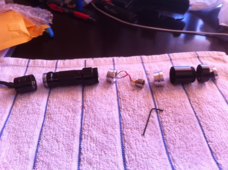
The image above shows from left to right: 1) Tail cap clicky, 2) Main body, 3) Pill containing the driver with leads attached to the diode inside an Aixiz module, 4) Diode heat sink with allen wrench, 5) Heat sink holder, 6) Heat sink retaining ring, and 7) 3 element glass lens with focus adjuster attached.

2b7769f3.jpg


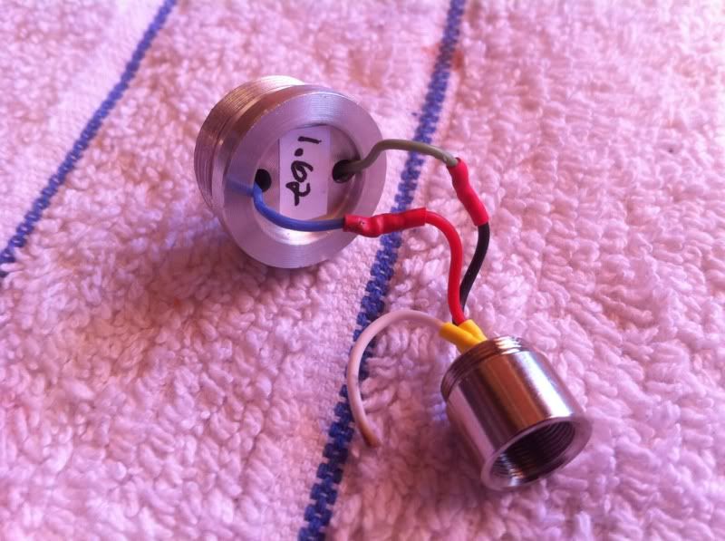
The image above shows the pill containing the driver and how I wired it to the diode leads from the diode/Aixiz module. Leads to the diode itself were soldered by DTR.

The pill is clearly marked with the driver output current from Mohrenberg at 1.62A. Both the driver wires and the lead wires from DTR's diode were about twice as long as shown here. In other words I cut the lengths down by about half.

Then I soldered the driver leads to the diode leads and applied heat shrink tubing to secure and insulate the connections. I left the white case wire as long as I did in case it is ever needed in a different application. I used a match and slightly melted the end of the white wire to prevent any ugly surprises.

And now some eye-candy...


This is a burning little beast. Hope you enjoy the pictures. This is my first ever build that included a soldering job.

Glenn
 
Last edited:


Joined
Nov 8, 2011
Messages
404
Points
28
Re: Assembly of C6 Host & DTR 445nm Diode

Very nice. All you need now is some beam shots :wave:
 
Joined
Aug 30, 2008
Messages
6,891
Points
83
Re: Assembly of C6 Host & DTR 445nm Diode

Nice!

Labeling the pills like that was done for my own sanity. I knew if i didn't label them, i'd put them together only to forget what driver they had in them :crackup:

I'm going to make the heat sinks fill the entire head in the future. I had been making them short because there needed to be room to mount the driver on top of the pill. Since I have the round driver now that pop right into the pill, all of that spare room can go towards heat sinking.
 
Joined
Dec 11, 2011
Messages
4,364
Points
83
Very nice build!!! Beamshots are always the highlight for me, so add 'em if ya got 'em!
 
Joined
Aug 30, 2008
Messages
6,891
Points
83
yeah i am down to just blue and green. so i use blue for positive and green for negative.
 
Joined
Dec 11, 2011
Messages
4,364
Points
83
By the way, I forgot to mention; be careful what you use for a beamstop! I've burned holes in my wooden closet door with my 1.3W'er... 1.7W will only do it faster!
 
D

Deleted member 22482

Guest
Thank you for your little "guide". I don't how I am going to do it for the first time, I bought a kit from Moh at 1.62A aswell and I don't know if I should buy the diode already in a module with leads soldered or just the diode itself.. It's a hard choice.. What would you recommend as a first build ever? I'm thinking to just buy the diode and do it myself but the last thing I want is ruining my diode.. And how do I know which pin is positive and negative on the diode? I have seen those schemes someone posted, but there doesn't seem to be anything that clearly shows how it is done..

It looks like this V where the bottom is the neutral, one end of the V is positive and the other one is negative. How'd you know which of the edges is positive/negative?

Thanks.
 
Last edited by a moderator:

DTR

0
Joined
Jun 24, 2010
Messages
5,684
Points
113
Great job. Now that was easy wasn't it.:beer:


Thank you for your little "guide". I don't how I am going to do it for the first time, I bought a kit from Moh at 1.62A aswell and I don't know if I should buy the diode already in a module with leads soldered or just the diode itself.. It's a hard choice.. What would you recommend as a first build ever? I'm thinking to just buy the diode and do it myself but the last thing I want is ruining my diode.. And how do I know which pin is positive and negative on the diode? I have seen those schemes someone posted, but there doesn't seem to be anything that clearly shows how it is done..

It looks like this V where the bottom is the neutral, one end of the V is positive and the other one is negative. How'd you know which of the edges is positive/negative?

Thanks.

It really is not that bad if you are comfortable with soldering. You would just find something that can press your diode. Some use broken antennas or someting similar that can push the diode in past flush for best contact. I use a press tool from Flaminpyro that works great. Then here is the pinout of the diode.:beer:

10.gif
 
Last edited:

jimdt7

0
Joined
Feb 5, 2011
Messages
1,893
Points
48
Nice build man !
You have a real burner in you hands :p
+1 :beer:

Jim
 
Joined
Nov 19, 2011
Messages
294
Points
0
For the build in this thread I got the diode from DTR already pressed into the module with leads and the G2 lens.

For the next one I think I will just get the bare diode and see if I can do one from scratch without screwing anything up. If your soldering skills are decent and you have a method to press the diode you should be able to do it.

Glenn

Thank you for your little "guide". I don't how I am going to do it for the first time, I bought a kit from Moh at 1.62A aswell and I don't know if I should buy the diode already in a module with leads soldered or just the diode itself.. It's a hard choice.. What would you recommend as a first build ever? I'm thinking to just buy the diode and do it myself but the last thing I want is ruining my diode.. And how do I know which pin is positive and negative on the diode? I have seen those schemes someone posted, but there doesn't seem to be anything that clearly shows how it is done..

It looks like this V where the bottom is the neutral, one end of the V is positive and the other one is negative. How'd you know which of the edges is positive/negative?

Thanks.
 
Joined
Nov 19, 2011
Messages
294
Points
0
I was thinking of using a 12" x 12" piece of ceramic tile painted black for a beam stop.

What are some other methods of a beam stop?

Thanks.

Glenn


By the way, I forgot to mention; be careful what you use for a beamstop! I've burned holes in my wooden closet door with my 1.3W'er... 1.7W will only do it faster!
 

Joe Mo

0
Joined
Jan 4, 2012
Messages
317
Points
0
Great job Glenn, this is how I want to do my first build, with the same host/wavelength.
 
Last edited:

Stix62

0
Joined
Dec 29, 2011
Messages
463
Points
0
Good thread and job well done.

I've been thinking about a first build but there were a few simple things I wasn't quite sure about. I was on the right track though and your thread and pictures have confirmed it - thanks.

Very inspirational - it looks so easy :D


Top