Welcome to Laser Pointer Forums - discuss green laser pointers, blue laser pointers, and all types of lasers
How to Register on LPF | LPF Donations
Navigation
Install the app
How to install the app on iOS
Follow along with the video below to see how to install our site as a web app on your home screen.
Note: This feature may not be available in some browsers.
More options

You are using an out of date browser. It may not display this or other websites correctly.
You should upgrade or use an alternative browser.
You should upgrade or use an alternative browser.
800mw 532nm module
- Thread starter badboybilly
- Start date


- Joined
- Mar 5, 2015
- Messages
- 1,333
- Points
- 113
- Joined
- Oct 14, 2012
- Messages
- 6,086
- Points
- 113
Coming along nicely, bbb! I'm sure it'll be a sweet looking, unique host!
BobMc
0
- Joined
- Apr 23, 2016
- Messages
- 3,683
- Points
- 113
As always very impressive. As you get closer to completion does your heart start to beat faster? Mine always seem too. :gj: and looking forward to seeing it brought to life. 
- Joined
- Mar 5, 2015
- Messages
- 1,333
- Points
- 113
As always very impressive. As you get closer to completion does your heart start to beat faster? Mine always seem too. :gj: and looking forward to seeing it brought to life.
I'm not sure about my heart but until the laser is exceptional, I'm not pleased, and when it is I'm extremely happy!
Attachments
Last edited:
BobMc
0
- Joined
- Apr 23, 2016
- Messages
- 3,683
- Points
- 113
I'm not sure about my heart but until the laser is exceptional, I'm not pleased, and when it is I'm extremely happy!
Your work does give you reason to be proud. :bowdown:
Are you planning on putting a potentiometer on it?
- Joined
- Mar 5, 2015
- Messages
- 1,333
- Points
- 113
Your work does give you reason to be proud. :bowdown:
Are you planning on putting a potentiometer on it?
Not this one Bob!
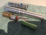
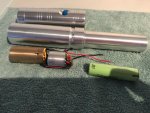
I'm hoping there is enough room for the driver pill module and contact board and the 3cm space I need between the module and collimation lens it's going to be tough enough as it is, Another thing worrying me is David mentioned it's ok to give the module 4.5v none of our batteries can supply 4.5v so I'm really hoping a normal IMR will do the job for the full 800mw + output, If not then this module is only good for a desktop laser. Or possibly 2 batts and a step down voltage regulator, Will soon find out!
RB astro
0
- Joined
- Apr 6, 2014
- Messages
- 2,436
- Points
- 113
Very exciting to follow the progress Billy.
My heart's pacing.
Can't wait mate.
Looking beautiful so far.
RB
:beer:
My heart's pacing.
Can't wait mate.
Looking beautiful so far.
RB
:beer:
- Joined
- Mar 5, 2015
- Messages
- 1,333
- Points
- 113
Very exciting to follow the progress Billy.
My heart's pacing.
Can't wait mate.
Looking beautiful so far.
RB
:beer:
Hey Andrew
Thanks buddy I can only do a bit here and there just no time but it's coming along, I really hope in the end turns out 800mw + like promised, that is the most important aspect it's what I paid for,
I'll be honest the disappointment is comming from the first quick power test that only showed 400mw and this was without collimation or IR filter witch sounds even worse, However the transistor was not heatsinked, it was only a 5 second run and bat wasn't fully charged. I was told I could use 4.5v but if that is what it needs to hit max power then I've got a problem, Also soldering on the driver was done rough, wire from driver to module was only holding on by one strand hopefully contributing to the lower power! Anyway housing for these modules need to be built well in order for everything to work as intended, it's coming together and we will know shortly,
https://youtu.be/q-c97LxQbkc
Last edited:
RB astro
0
- Joined
- Apr 6, 2014
- Messages
- 2,436
- Points
- 113
Yeah, I can imagine it's initially disappointing but hang in there till it's all put together.
:beer:
:beer:
D
Deleted member 17304
Guest
Is this one case positive? I'm guessing your driver is OK with that and you don't need anything isolated? Mine needed to be isolated from the host with thermal tape and nylon tipped set screws... If you don't have to isolate anything, this seems a lot easier than my custom jayrob 473 and 532 were...
Looking forward to seeing a finished product!
Looking forward to seeing a finished product!
- Joined
- Sep 20, 2013
- Messages
- 20,284
- Points
- 113
Zach, couldn't you just reverse the battery polarity for the case positive builds? Only time it becomes an issue for me is when the driver is not positive leg continuous.
- Joined
- Mar 5, 2015
- Messages
- 1,333
- Points
- 113
Is this one case positive? I'm guessing your driver is OK with that and you don't need anything isolated? Mine needed to be isolated from the host with thermal tape and nylon tipped set screws... If you don't have to isolate anything, this seems a lot easier than my custom jayrob 473 and 532 were...
Looking forward to seeing a finished product!
I've made sure the driver doesn't make contact with the housing either way!
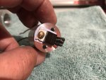
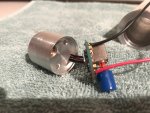
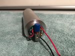
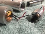
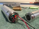
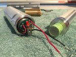
It's obvious in the pics the transistor is isolated with thermal tape and nylon washer, Easier than paying jayrob for a custom built housing and module, I doubt it, but if you have a lathe and experience it comes naturally and yes it is easy! Finding the time is the hard part!
D
Deleted member 17304
Guest
Zach, couldn't you just reverse the battery polarity for the case positive builds? Only time it becomes an issue for me is when the driver is not positive leg continuous.
With the way the switch was set up on the host I had it was not possible - the button only worked with current on the way back from the module. It was a vintage flashlight from the 50s. Positive end of battery touches the bulb, negative end from bulb to button terminal, then other side of button to the host. I can draw something up tonight if words don't clarify enough
--
But that's good Billy that you were able to isolate the driver. Nice and simple that way
- Joined
- Sep 20, 2013
- Messages
- 20,284
- Points
- 113
You needn't draw a picture. I see what you are saying. Funny thing about 1950s flashlights...... the battery polarity didn't matter as the bulb didn't care which way current flowed through it.
- Joined
- Mar 5, 2015
- Messages
- 1,333
- Points
- 113


