

- Joined
- Jun 12, 2015
- Messages
- 7,769
- Points
- 113
Hi everyone, it’s about time I finally post a build on here after all these years.
It is the first time I have ever completed a portable before. I have contemplated portables before but never got round to it. I tend to stick with wiring power adaptors on usually because I love the run times and better heat management. But since this laser is such a brilliant wavelength I found it too much of a shame to keep into reined to plug sockets. So in true fashion I have managed to create a laser host that is both a portable and a lab.
Warning – thread will be pic-heavy.
About the laser:
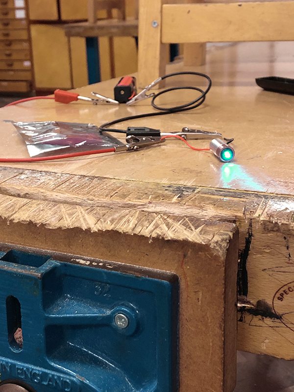
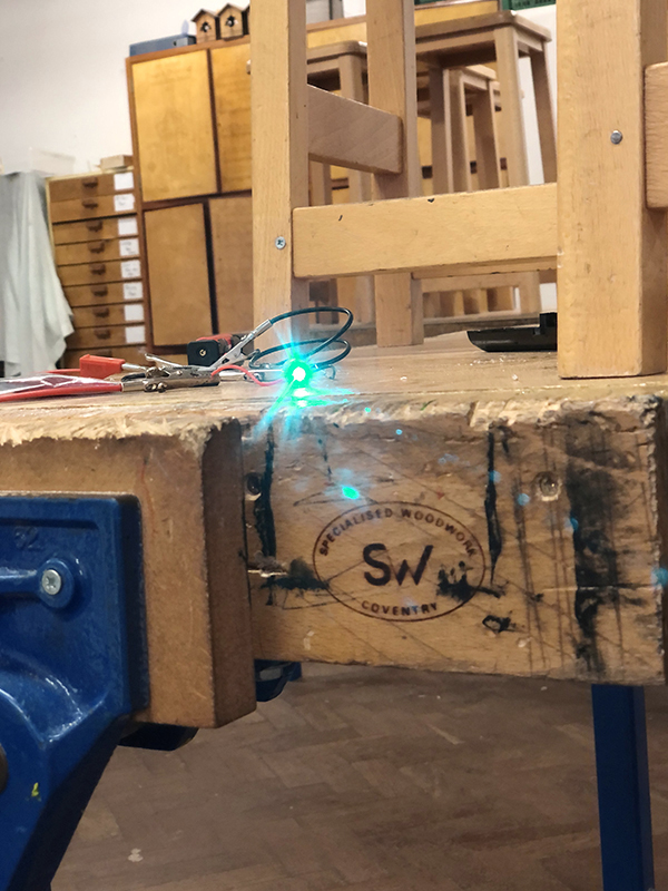
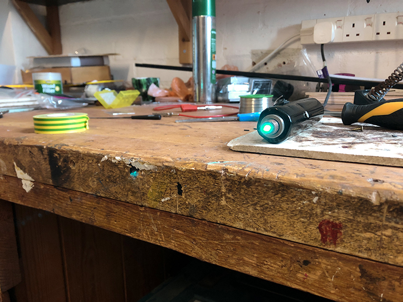
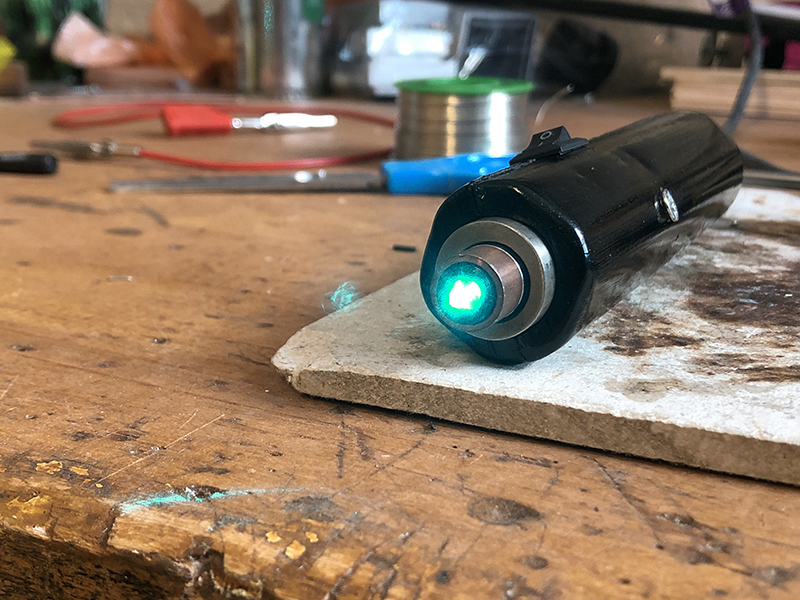
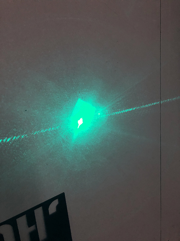
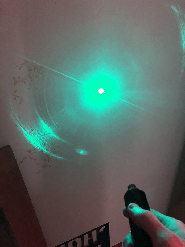
The diode is a Sharp GH04850B2G (SB308B292) powered by an Astral Picodrive set at 220mA. Output is reported to be 110mW with a G2 lens, but I have an acrylic. The diode was generously gifted to me by Chris (Alaskan) who bought it on my behalf from Corey (jnrpop). It was listed as 491nm however I have found that it is closer to 493nm. This hasn’t presented a problem however as the wavelength is exotic and stunning. In fact it goes very nicely with my other laser featuring a Sharp GH04850B2G (SB308B292). Giving me the better range in the cyan part of the spectrum.
Design stage:
The first thing I had to set out to do was get to work on designing the host. The most difficult thing to combat was lack of funds and resources. I do however own a 3D printer. 3D printers are amazing machines however as anyone that has experienced using one has probably found. Tolerance and certain design considerations due to the manufacturing process have to be taken into account. I originally was going to get a cheap flashlight host, but decided against it. What you buy is what you get so you didn’t have the freedom to openly adapt the design and I wanted to make my first build a little more special. I also wanted to have the best of both worlds with the host. Portability and lab capabilities.
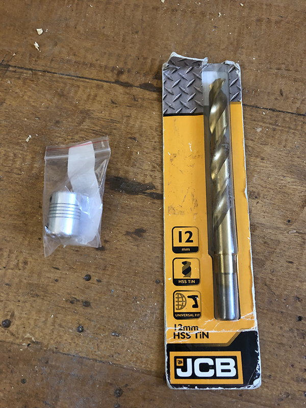
This is the final CAD design that I settled on, the idea was simple. The host is made in two parts. A top and bottom that will interlock. The bottom contains the mounts for the components, whilst the top just encapsulates. To create the battery contact points, I have an 18650 battery holder. I have a basic small locking switch to turn the laser constantly on/off. An aluminium shaft coupler to act as an appropriate sized heatsink. They only went up to 10mm diameter so I had to buy a 12mm drill bit and drill it out to take the 12mm module. And to incorporate lab like abilities I have a Micro-USB 18650 charging circuit which allows the unit to charge by a USB lead without having to remove the battery. It also allows the laser to be used whilst you supply input power. Unlike other incorporated li-ion devices, which I have heard criticism for. The battery is accessible and replaceable. I will also every now and then charge the battery up in my XTAR charger to ensure the battery life is maintained.
Manufacturing Stage:
Once the CAD files were finalised and checked for any geometry issues I exported the STL files ready to send to the printer. The host material is black PLA.
The host took around 3 hours to print at standard quality. There was no point in raising the print quality as I already had intentions to do some hand finishing. And the internals would need potentially adjustments to make sure everything fits.
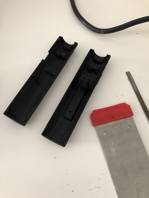
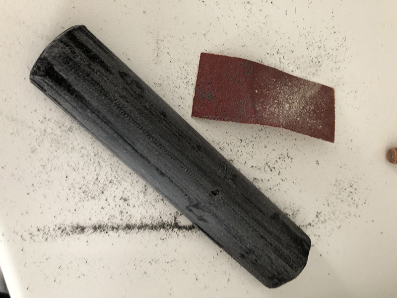
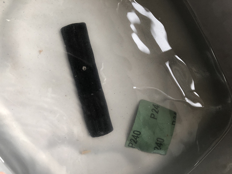
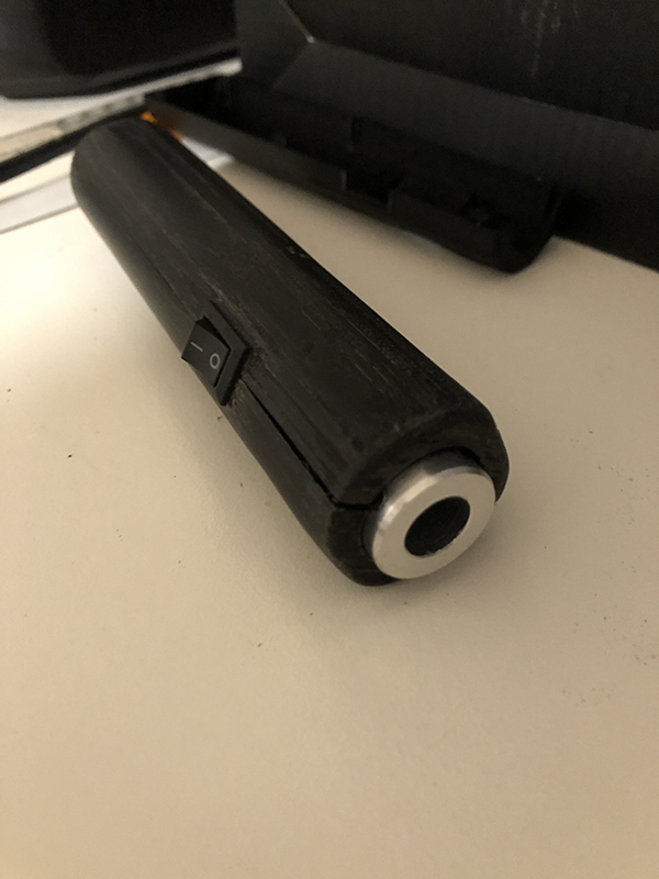
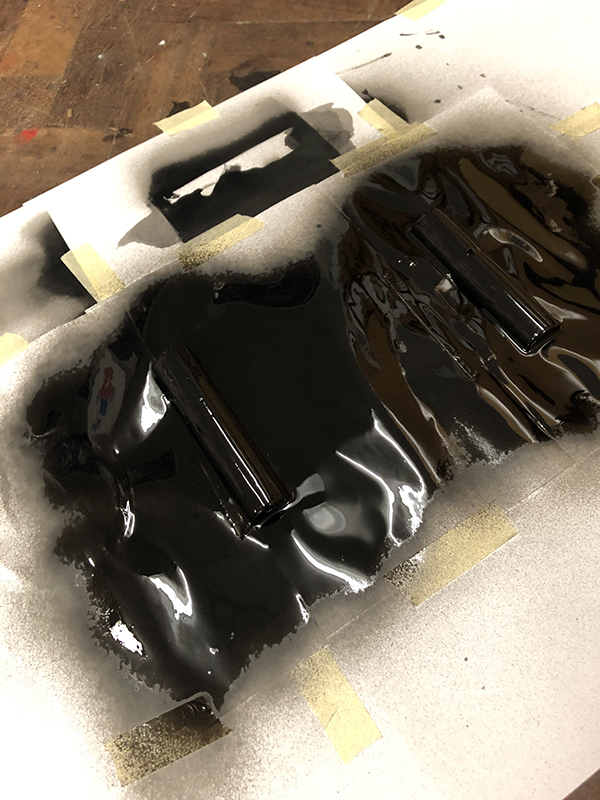
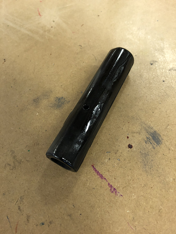
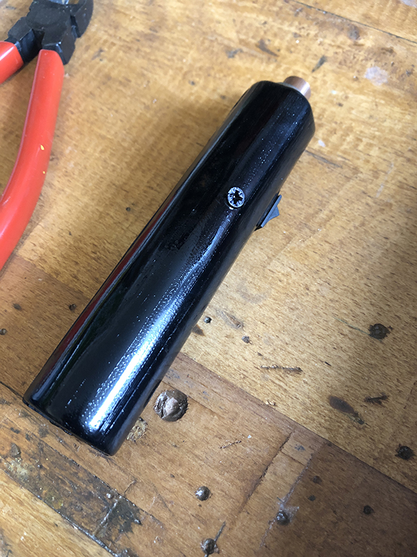
Due to the layers, 3D prints can often be rough and not very tactile. I began to correct that by using coarse sandpaper and carefully taking the surface defects down. I then moved down the grades until I got onto wet and dry. The host still has visual defects present however it is now smooth to touch
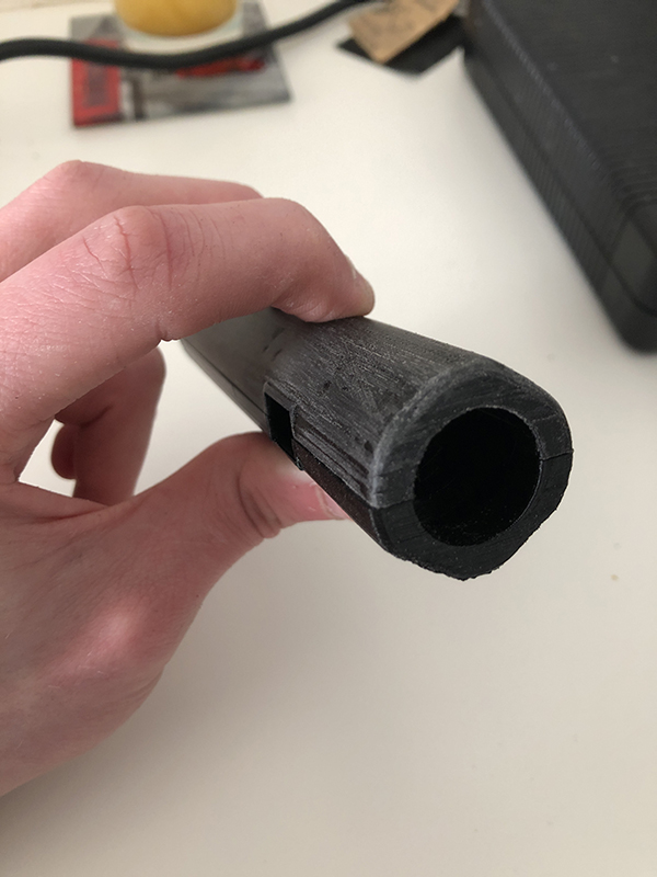
and comfortable to hold.
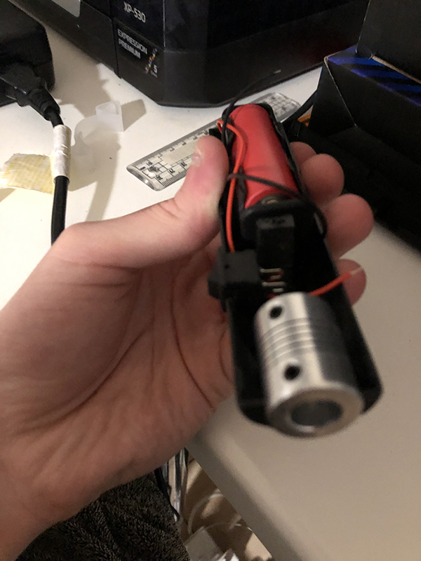
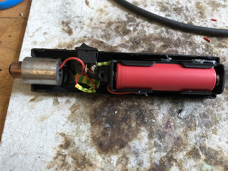
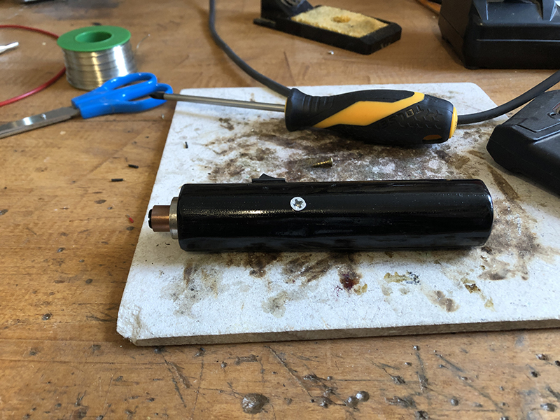
The next step is the internals and making sure the key components fit inside the host. I had to file the switch holder to allow the switch to sit comfortably. The battery compartment was the perfect initially. The heatsink however didn’t allow the host to fit together properly. So a bit of filing was required there too. Here is the host together with components for the first time.
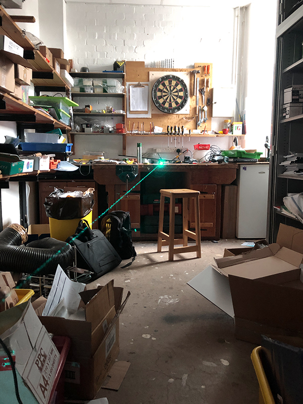
The rest of the build had to wait until I got back to work. I work in a school DT workshop, so that way I could have access to some of the tools and frankly some space to work.
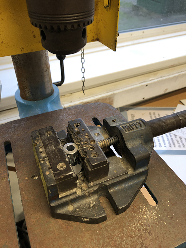
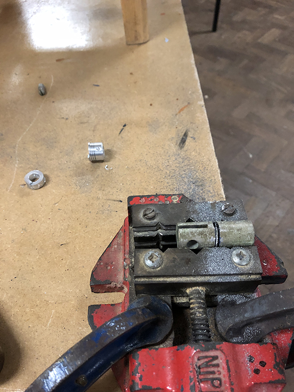
The first thing I started off doing was drilling that 12mm hole into my makeshift heatsink. And let’s just say that it wouldn’t be my way if things didn’t go wrong somewhere. I had accidentally ordered a flexible shaft coupler. And I naively thought that if I drilled it more carefully it wouldn’t make a difference. I started with an 11mm drill bit and that is as far as I got. The coupler split apart.
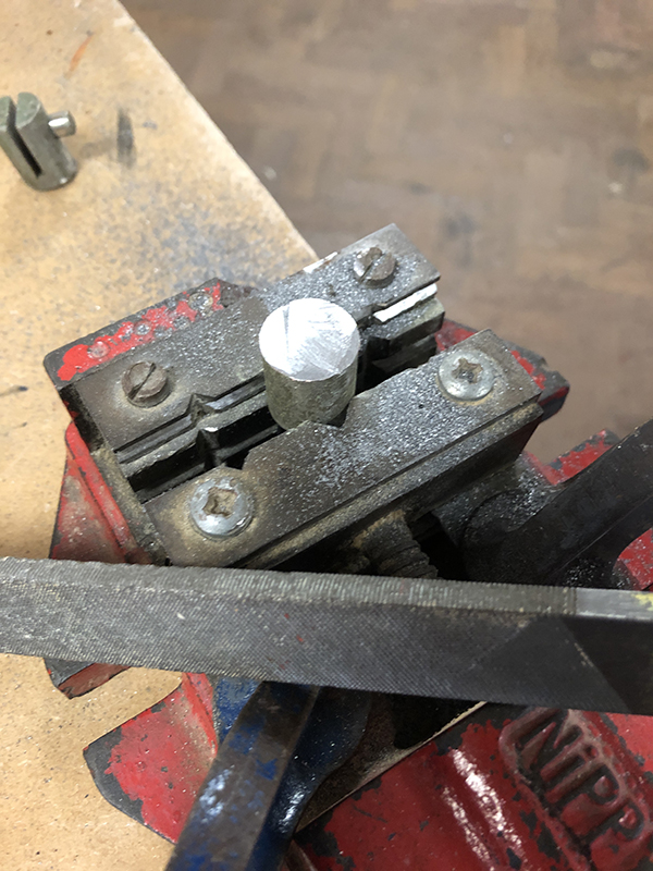
I had a full day ahead and thought the build was already doomed. Luckily I manage to find a piece of redundant steel that was the same diameter as the heatsink and had enough usable length. So I set to work cutting and filing it into a heatsink.
In the end I had to stop using the pillar drill to drill out the 12mm hole and opt for a regular cordless instead due to the torque. Annoyingly despite care the hole didn’t end up being perfectly centred. But considering only less than an hour ago I had nothing to work with it was better than nothing and saved the build.
Electronics stage:
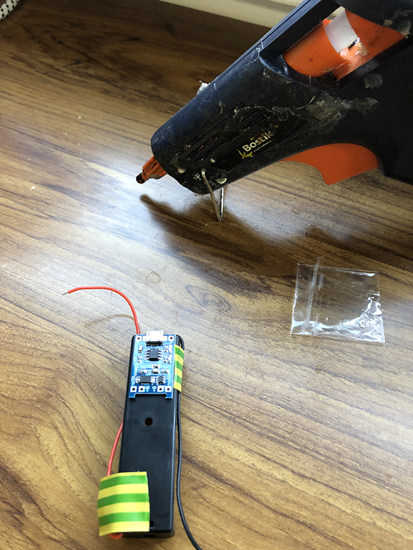
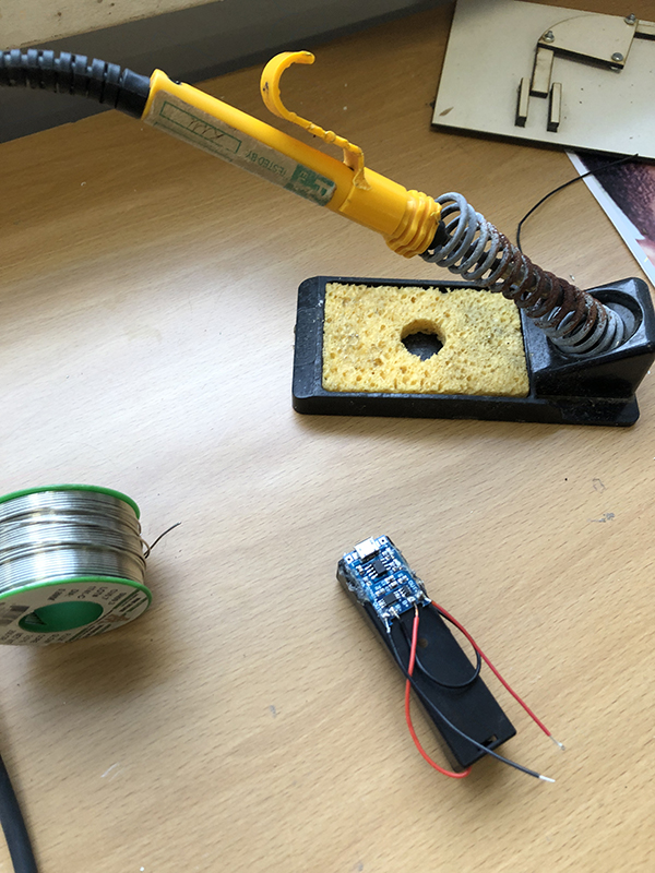
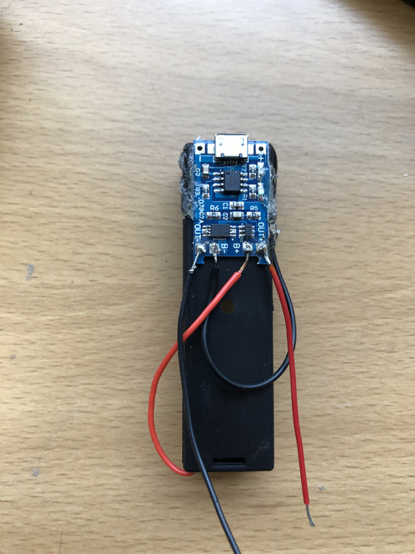
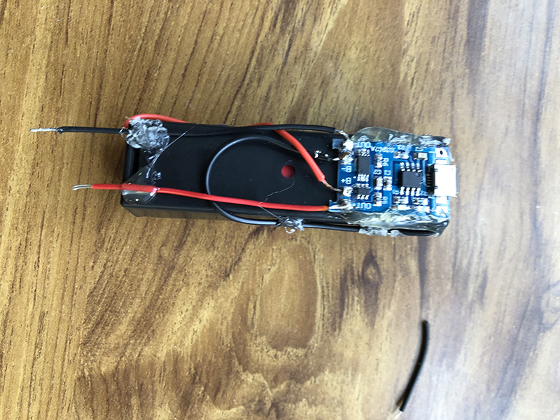
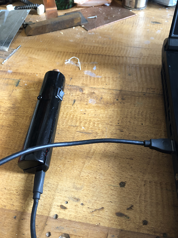
It was time to start getting the laser operational. I decided to begin on the li-ion charging circuit. I hot-glued the charging circuit to the bottom of the battery holder. I made sure I didn’t glue over any important contacts but also had to ensure the circuit couldn’t move around and could withstand having a Micro-USB cable being plugged in. Once the board was secure, I got to work soldering the leads to the appropriate contacts. The battery holder leads had to be soldered to the circuit board and then I had to solder two output leads.
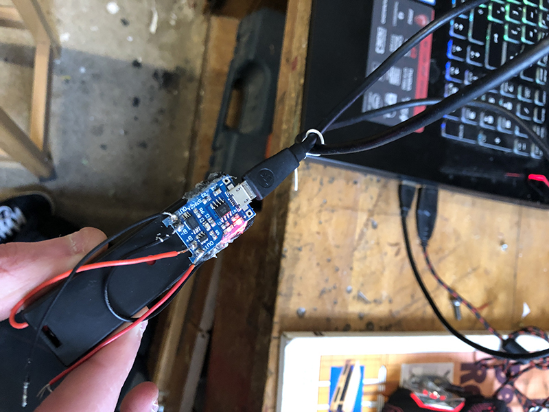
It was then important for me to check the circuit board out my both plugging it into my laptops USB port to ensure the battery could charge.
Build thread continued in next post.
It is the first time I have ever completed a portable before. I have contemplated portables before but never got round to it. I tend to stick with wiring power adaptors on usually because I love the run times and better heat management. But since this laser is such a brilliant wavelength I found it too much of a shame to keep into reined to plug sockets. So in true fashion I have managed to create a laser host that is both a portable and a lab.
Warning – thread will be pic-heavy.
About the laser:
The diode is a Sharp GH04850B2G (SB308B292) powered by an Astral Picodrive set at 220mA. Output is reported to be 110mW with a G2 lens, but I have an acrylic. The diode was generously gifted to me by Chris (Alaskan) who bought it on my behalf from Corey (jnrpop). It was listed as 491nm however I have found that it is closer to 493nm. This hasn’t presented a problem however as the wavelength is exotic and stunning. In fact it goes very nicely with my other laser featuring a Sharp GH04850B2G (SB308B292). Giving me the better range in the cyan part of the spectrum.
Design stage:
The first thing I had to set out to do was get to work on designing the host. The most difficult thing to combat was lack of funds and resources. I do however own a 3D printer. 3D printers are amazing machines however as anyone that has experienced using one has probably found. Tolerance and certain design considerations due to the manufacturing process have to be taken into account. I originally was going to get a cheap flashlight host, but decided against it. What you buy is what you get so you didn’t have the freedom to openly adapt the design and I wanted to make my first build a little more special. I also wanted to have the best of both worlds with the host. Portability and lab capabilities.
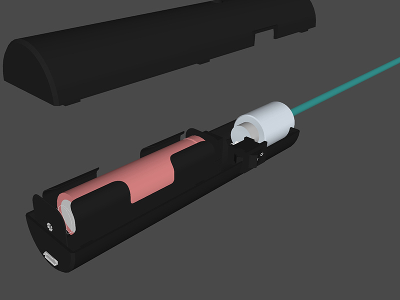
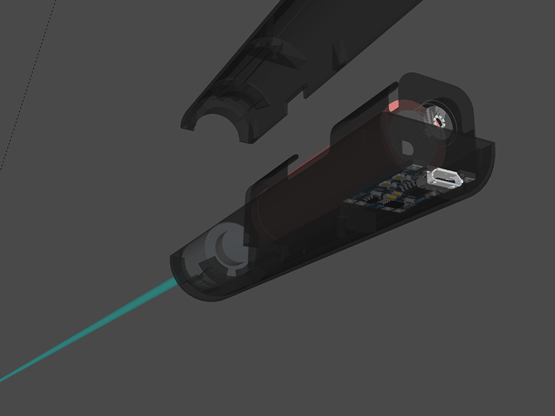
This is the final CAD design that I settled on, the idea was simple. The host is made in two parts. A top and bottom that will interlock. The bottom contains the mounts for the components, whilst the top just encapsulates. To create the battery contact points, I have an 18650 battery holder. I have a basic small locking switch to turn the laser constantly on/off. An aluminium shaft coupler to act as an appropriate sized heatsink. They only went up to 10mm diameter so I had to buy a 12mm drill bit and drill it out to take the 12mm module. And to incorporate lab like abilities I have a Micro-USB 18650 charging circuit which allows the unit to charge by a USB lead without having to remove the battery. It also allows the laser to be used whilst you supply input power. Unlike other incorporated li-ion devices, which I have heard criticism for. The battery is accessible and replaceable. I will also every now and then charge the battery up in my XTAR charger to ensure the battery life is maintained.
Manufacturing Stage:
Once the CAD files were finalised and checked for any geometry issues I exported the STL files ready to send to the printer. The host material is black PLA.
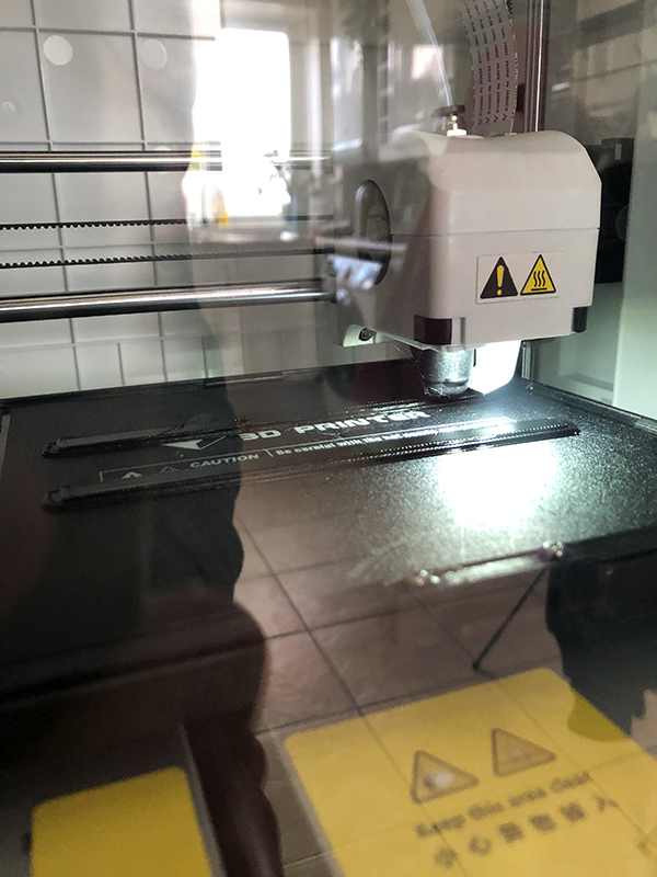
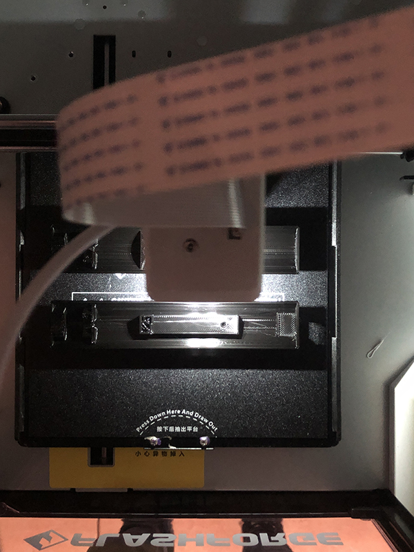
The host took around 3 hours to print at standard quality. There was no point in raising the print quality as I already had intentions to do some hand finishing. And the internals would need potentially adjustments to make sure everything fits.
Due to the layers, 3D prints can often be rough and not very tactile. I began to correct that by using coarse sandpaper and carefully taking the surface defects down. I then moved down the grades until I got onto wet and dry. The host still has visual defects present however it is now smooth to touch
and comfortable to hold.
The next step is the internals and making sure the key components fit inside the host. I had to file the switch holder to allow the switch to sit comfortably. The battery compartment was the perfect initially. The heatsink however didn’t allow the host to fit together properly. So a bit of filing was required there too. Here is the host together with components for the first time.
The rest of the build had to wait until I got back to work. I work in a school DT workshop, so that way I could have access to some of the tools and frankly some space to work.
The first thing I started off doing was drilling that 12mm hole into my makeshift heatsink. And let’s just say that it wouldn’t be my way if things didn’t go wrong somewhere. I had accidentally ordered a flexible shaft coupler. And I naively thought that if I drilled it more carefully it wouldn’t make a difference. I started with an 11mm drill bit and that is as far as I got. The coupler split apart.
I had a full day ahead and thought the build was already doomed. Luckily I manage to find a piece of redundant steel that was the same diameter as the heatsink and had enough usable length. So I set to work cutting and filing it into a heatsink.
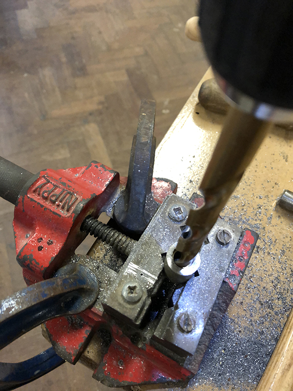
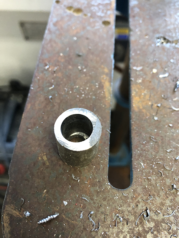
In the end I had to stop using the pillar drill to drill out the 12mm hole and opt for a regular cordless instead due to the torque. Annoyingly despite care the hole didn’t end up being perfectly centred. But considering only less than an hour ago I had nothing to work with it was better than nothing and saved the build.
Electronics stage:
It was time to start getting the laser operational. I decided to begin on the li-ion charging circuit. I hot-glued the charging circuit to the bottom of the battery holder. I made sure I didn’t glue over any important contacts but also had to ensure the circuit couldn’t move around and could withstand having a Micro-USB cable being plugged in. Once the board was secure, I got to work soldering the leads to the appropriate contacts. The battery holder leads had to be soldered to the circuit board and then I had to solder two output leads.
It was then important for me to check the circuit board out my both plugging it into my laptops USB port to ensure the battery could charge.
Build thread continued in next post.


")
")
