Welcome to Laser Pointer Forums - discuss green laser pointers, blue laser pointers, and all types of lasers

LPF Donation via Stripe | LPF Donation - Other Methods

Links below open in new window

ArcticMyst Security by Avery

40-50W blue laser from tightly packed parallel 08 beams

Joined
Feb 12, 2016
Messages
589
Points
63
Hi,
in this thread I want to summarize the experiments with aim to construct a 50W "laser cannon" build. This was result of thinking about what one can do with a virgin NUBM08 block.
How would you like to call this baby?

You can consider this thread as a continuation of that one called "Gatling laser":

but now I finally started the work to combine all these 8 corrected beams into one.

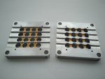
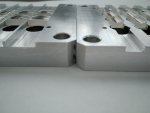
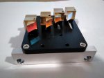
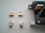
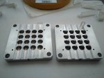
First of all, I needed to immobilise all C-lenses on perforated plates to avoid rotational artefacts. For this I made 2mm deep pitches exactly as wide as the lenses. This job had to be done twice until all the lenses fitted perfectly deep and parallel into pitches.
The fit was so tight that I did not even need to glue the lenses, double sided adhesive tape was enough to attach all of them.


Later working plan was as follows:

1. KE both upper and bottom rows horizontally to make 2 groups (left and right) well separated for PBSing at the end. This separation in the center needs to be because you cannot PBS 2 parallel beams if they are too close. This knife edging would also make all the beams parallel resolving possible issues from LDs not being properly installed in the block.

2. KE resulting beams vertically to reduce the gap to 4mm (this because if these were NUBM44 with collimation to infinity and not close range focused like some of these 08 with G-balls, the beams should be squares with 4mm hight and not lines like these).

3. PBS left and right groups at the end into one super ray directing it forward again!

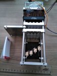
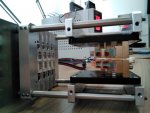
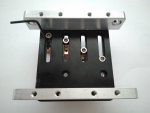
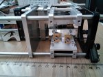
For the 1st knife edging I installed 2 assembled Lasertack micro KE modules on the existing Thorlabs frame bars with aid of small custom made sliding adapters.

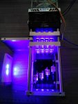
You can see that after this the beams were reflected to the right and formed a rectangle with 12mm horizontal and 10mm vertical separation between beam centers (pic. 8). The spots are not square and not all the same because this NUBM08 block had all LDs with slightly different collimation by G-balls in place...

to be contnued...01 C-holders.jpg02 tape.jpg03 cylindricals.jpg04 mirrors set.jpg05 2 beams.jpg06 sliding mount.jpg07 horiz shift mirrors.jpg08 square packing.jpg


Joined
Jun 3, 2007
Messages
2,560
Points
113
Hi,
in this thread I want to summarize the experiments with aim to construct a 50W "laser cannon" build. This was result of thinking about what one can do with a virgin NUBM08 block.
How would you like to call this baby?

You can consider this thread as a continuation of that one called "Gatling laser":

but now I finally started the work to combine all these 8 corrected beams into one.

First of all, I needed to immobilise all C-lenses on perforated plates to avoid rotational artefacts. For this I made 2mm deep pitches exactly as wide as the lenses. This job had to be done twice until all the lenses fitted perfectly deep and parallel into pitches.
The fit was so tight that I did not even need to glue the lenses, double sided adhesive tape was enough to attach all of them.


Later working plan was as follows:

1. KE both upper and bottom rows horizontally to make 2 groups (left and right) well separated for PBSing at the end. This separation in the center needs to be because you cannot PBS 2 parallel beams if they are too close. This knife edging would also make all the beams parallel resolving possible issues from LDs not being properly installed in the block.

2. KE resulting beams vertically to reduce the gap to 4mm (this because if these were NUBM44 with collimation to infinity and not close range focused like some of these 08 with G-balls, the beams should be squares with 4mm hight and not lines like these).

3. PBS left and right groups at the end into one super ray directing it forward again!

For the 1st knife edging I installed 2 assembled Lasertack micro KE modules on the existing Thorlabs frame bars with aid of small custom made sliding adapters.

You can see that after this the beams were reflected to the right and formed a rectangle with 12mm horizontal and 10mm vertical separation between beam centers (pic. 8). The spots are not square and not all the same because this NUBM08 block had all LDs with slightly different collimation by G-balls in place...

to be contnued...View attachment 65668View attachment 65669View attachment 65670View attachment 65671View attachment 65672View attachment 65673View attachment 65674View attachment 65675
Take a look at the 200W Laser Bazooka.
 
Joined
Feb 12, 2016
Messages
589
Points
63
Do no say that you think it is the same type of build, Steve!

Light engines from A-series are real crap, even after factory knife edging thise 24 uncorrected beams look more like a torch than a laser.

I tried to burn wood with one of them and after PCX lens the minimum spot of this "knife-edged death ray" was 1cm2 large even at 20cm range, not saying about long distances.

But filming in the dark room with a little smoke looks fantastic, even if we know it is cheating like Holly/Bollywood do for the masses...

Once I have finished my laser I might put it into a Leaf blower body, I doubt that there is anything else in the world what it could pass into.
 
Joined
Jun 3, 2007
Messages
2,560
Points
113
Do no say that you think it is the same type of build, Steve!

Light engines from A-series are real crap, even after factory knife edging thise 24 uncorrected beams look more like a torch than a laser.

I tried to burn wood with one of them and after PCX lens the minimum spot of this "knife-edged death ray" was 1cm2 large even at 20cm range, not saying about long distances.

But filming in the dark room with a little smoke looks fantastic, even if we know it is cheating like Holly/Bollywood do for the masses...

Once I have finished my laser I might put it into a Leaf blower body, I doubt that there is anything else in the world what it could pass into.
I don't remember. Styropyro I think explains the build.
 
Joined
Jan 29, 2014
Messages
12,031
Points
113
Styro's lazer bazooka did not have beam alignment of any kind, it was just the light strait out of a diode block. If you watch that video, you can see some of the beams are not pointing together out of the large focusing lens. He builds stuff for sensationalism to get more clicks, doesn't do this kind of engineering.
 
Joined
Feb 12, 2016
Messages
589
Points
63
Yes, my sensationalism is burning white walls far away with pens, not popping close black balloons with bazookas!!!

Back to the subject:
For the 2nd vertical knife edging I attached (due to big contact surface adhesive tape was OK here as well) two 20x10mm RGB HR mirrors from Optlasers to small 45º wedge plates positioned onto same type of sliding adapters used to move Lasertack micro baseplates earlier. All these custom parts were made especially for this build.
Since the beams propagate to the right now, 2 more Thorlabs bars were added, so it makes now 2 adjacent 60mm cages parallel to each other.


In such a construction 2 issues had to be fixed:

1. Shaking of the bars - to resolve it I hardened the bars structure by putting more of custom made blank Al plates on the frame.

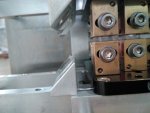
2. Need to adjust beam directions by rotating the prism mirrors - with Al bar installed from the front there was no way to rotate Lasertack mirror holders because the holes were no more accessble. So I made more holes on bottom of the mounts (pic.10 from the start of this build) after what the holders could be adjusted through the long bottom holes of baseplates (pic.11).


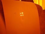
After all this the spot (checked at <0.5A current, otherwise cardboard burns!) shows 2 12mm separated parallel beams each consisting of 4 original 08 beams. Separation between each beam´s low and upper components is 4mm.

to be continued...


09 vertical shift mirrors.jpg10 add holes.jpg11 add holes.jpg12.jpg13 4mm offset.jpg
 
Joined
Feb 25, 2010
Messages
1,643
Points
113
HOLY SHIT !!!!....THIS IS INSANE !!! I must study this !!! Vladimir.....I am deeply Impressed !!!
OK..... Further explain your beam paths !!!!! PLEASE !!!...….
I am confused !!! 16 LD's.....right......WHAT A BEAUTY !!!!!!!!!!!!!!!!!!!!!!!!! Built like a tank..... I am completely blown away !!!

Hmmmm ????

Knife edge 4 LD's....Stack 4 atop 4...so 8 LD in the bundle....then PBS 8 + 8....so 16 LD total.... My head is spinning !!!

Hmmmm ??? For a name....my suggestion..." The Indigo Interocitor " Later, CDB
 
Joined
Jan 29, 2014
Messages
12,031
Points
113
I feel the same way about his project, I didn't give it the praise it deserves.
 
Joined
Sep 20, 2013
Messages
17,424
Points
113
You are the only member I know that is doing so much with KEing these days. I also enjoy seeing what you have come up with next. Great work!
 
Joined
Feb 12, 2016
Messages
589
Points
63
Hi Bob,
where did you find 16 beams? There are only 8 beams in this block. Please take a precise look into pictures, I hope that I have explained all well, no?

Of course at start I wanted to make 16-beams combiner and bored 16 holes in the plates but from engineering point of view it was difficult to design parts which would fit inside of commercially available 60mm cage. Also this small HS with fan would not be enough for 2 blocks side by side. Not to mention the need for 2x more optics and mounts...

So, I started with 8 beams here to prove the concept.
Ouput of the block - 8 beams (this is starting point)
| space | space | space |

| space | space | space |

all beams are corrected by pairs of cylindricals and all pairs of neighbouring beams are knife edged to have 4 bundles (step 1)
OO space OO

OO space OO

the bundles are then squeezed by vertical knife edging (step 2)
OO space OO
OO space OO

and finally these 2 resulting thick beams combined by PBS into one (step 3)
OO
OO

Tomorrow I will add pictures about the 3rd step.
 
Last edited:
Joined
Jan 29, 2014
Messages
12,031
Points
113
Envious, I've bought four knife edge assemblies and lasertac mirrors, but as many projects, still waiting.
 
Joined
Feb 25, 2010
Messages
1,643
Points
113
Thanx Vladimir..... I think I understand now !! ( As though his ape's brain could understand the Secrets of the Krell ) hahahahha !!!

What a beautiful project......Superb !!

SO.... Do keep up the Updates !!!

Bob
 
Joined
Feb 12, 2016
Messages
589
Points
63
So, here is the last part of build description.

The 3rd thing was to combine the 2 resulting beams by PBS cube.
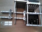
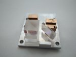
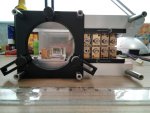
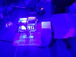
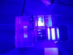
For this I made a small 3mm thick baseplate and screwed it to the same bottom sliding adapter which was bearing one of the wedge plates for 45º inclinated mirrors. Its design was tought to ensure that with 12mm PBS cube on Lasertack micro mirror mount the laterally incident beam will be reflected forward again and stay in the center of the 60mm cage. Of course only in horizontal projection, not vertically. But even if the resulted beam does not coinside with the optical axis, it could be later focused by lenses or expanded by a properly placed beam expander...

Here 12mm PBS cube from Techhood was used along with WP and third RGB HR mirror from Optlasers (I had to cut a little the latter to make it fit between screws).

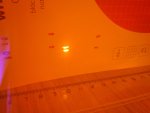
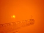
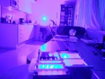
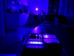
The combined beam is now 5x5mm at the PBS issue (pic. 17) and makes 20x20 mm spot on the wall at 5m away if the current is 2A (pic.18 and further). The beam is well visible in the dark.

Here again the mirror, WP and PBS are attached on adhesive tape, not with proper glue. This seems fine except for PBS cube what I have to adjust the position from time to time...

Current feed to the NUBM08 block is regulated by a cheap BST400W booster driver (Aliexpress) feeded from generic 12V 15A max. AC-DC input, this has been working fine up to now.

14.jpg15.jpg16.jpg17 50cm.jpg18 5m.jpg19 (2A).jpg20 (2A).jpg21 (2A).jpg22 (2A).jpg
 
Joined
Feb 25, 2010
Messages
1,643
Points
113
EPIC BUILD !!!!!!!!!!!! …" You graduate...you get the Job "….but ...CAN IT POP A BALLOON ???

CDB


Top