Welcome to Laser Pointer Forums - discuss green laser pointers, blue laser pointers, and all types of lasers

LPF Donation via Stripe | LPF Donation - Other Methods

Links below open in new window

ArcticMyst Security by Avery

Three (3 ) Axis Adjustable LD Mount

Joined
Dec 9, 2011
Messages
221
Points
28
HEY LOG, What is this supposed to be ?

What I posted earlier. Maybe you missed it.

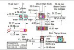
"Here is the back of a 10X P73 combiner I was just prototyping. It worked pretty good. Rotation is still a bit finicky but can be done with some patience. On the plate that holds the diode I cut a slot and drilled two holes. The slot allows me to use a small pliers to set rotation and the holes allow a small screwdriver to "push" the diode left or right. This is all the adjustment needed to align 10 diodes with 6X cyl correction. Of course there are probably a million ways to do it. This example is just one."

Basically just showing how simple it is to make a mount the allows X,Y translation of the diode and therefore correcting the angle the beam leaves the lens.

I think I might still be missing something. That is why i asked originally. But it seems people are looking to have the beam exit straight or some form of adjustment of the beam angle to allow correction and expansion after the collimator. Im trying to show/ explain the method I used to do this.

I highly doubt that a person can perform 0.001mm resolution with "bare hands" (though such precision is not needed anyway to align the relative diode-lens position). Making the diode movable in xy have to be designed in such way, that the heat transfer is still good enough for a handheld device.

Singlemode

You can. It can be done with the type mount I show. Depending on the power of the collimation lens .001 probably not necessary. With a 2mm lens I would guess ~.005mm is needed to keep the beam straight and the spot from excessive aberrations. Heat transfer is fine with copper base material. On 9mm diodes the landing can be made to have more surface area.

Keep in mind if the beam angle is multiplied by the expanders. If you start with say .5 deg off axis after a 8x cylinder set-up its 4deg of then a 3x spherical expander its 12deg off! So, initial tolerances and allignment matter here. If it didn't we wouldn't be having this conversdation:beer:

Only high-end lathes or CNC machines can reach a precision of 0.001mm, a hand is not possible
Maybe you wrong

Yes it would be very hard to machine this tolerance. That is why you move the diode manually to line things up.

I wonder if you can get it smaller to fit the smaller diameter modules. Now that would be neat :beer:

Im sure it could be done. I have made modules with .75 inch diameter, 5.6 and 9mm diodes. Using smaller screws it could be .5 diameter.
 
Last edited:


Joined
Jun 25, 2017
Messages
349
Points
63
You can. It can be done with the type mount I show. Depending on the power of the collimation lens .001 probably not necessary. With a 2mm lens I would guess ~.005mm is needed to keep the beam straight and the spot from excessive aberrations. Heat transfer is fine with copper base material. On 9mm diodes the landing can be made to have more surface area.

Keep in mind if the beam angle is multiplied by the expanders. If you start with say .5 deg off axis after a 8x cylinder set-up its 4deg of then a 3x spherical expander its 12deg off! So, initial tolerances and allignment matter here. If it didn't we wouldn't be having this conversdation:beer:

I am willing to bet (and spend my winnings to the LPF) that you are not able adjust with 0.001mm (even 0.01mm). You definitely can find a position where the beam is straight over the length you are looking, but has nothing to do with precision.


Best
Singlemode
 
Joined
Dec 9, 2011
Messages
221
Points
28
I am willing to bet (and spend my winnings to the LPF) that you are not able adjust with 0.001mm (even 0.01mm). You definitely can find a position where the beam is straight over the length you are looking, but has nothing to do with precision.


Best
Singlemode

I'm not exactly sure what you are getting at.

You definitely can find a position where the beam is straight over the length you are looking

Isn't this the important part? Is this not what we are trying to accomplish?

If you mean you can't know if the diode is "exactly" in the middle. This is true without special equipment.

But if you mean that the diode can't be moved with .01mm resolution relative to the lens by hand (with a screwdriver) then bet on.

What do you wager? :yh:
 
Joined
Jun 25, 2017
Messages
349
Points
63
I'm not exactly sure what you are getting at.


Isn't this the important part? Is this not what we are trying to accomplish?


You claimed that you can position with 0.001mm precision, and I don't believe it neither I think it is necessary.


If you mean you can't know if the diode is "exactly" in the middle. This is true without special equipment.

But if you mean that the diode can't be moved with .01mm resolution relative to the lens by hand (with a screwdriver) then bet on.

What do you wager? :yh:


20$, here the definition of precision:
https://en.m.wikipedia.org/wiki/Accuracy_and_precision


Singlemode
 
Joined
Dec 9, 2011
Messages
221
Points
28
20$, here the definition of precision:
https://en.m.wikipedia.org/wiki/Accuracy_and_precision


Singlemode

It sounds like you want to argue semantics. That is kinda lame as I said in my rant earlier.

Anyway. I figured I would use my time more productively.

I built a 3/4" round test rig for someone here to try. (link to pics at bottom)

Basically its a simple mount with M9 .5 threads on each end. One end is for the diode and lens. On the other end a BE can be screwed in. It has a flat milled out to place cylinders.

The diode is placed in a copper holder and is clamped in with a screw. Then the holder is screwed to the aluminum body. The mount should have very good thermal conductivity. However, there is not much surface area or mass to the body. Long term heat build up will be a problem unless this is mounted to a heatsink of some kind. It should work well as a test platform for alignment though.

Note: the picture shows an old 3W 445 with the lens attached. This is is the only free 9mm diode I had free. The mound is meant to be used with a separate 9mm lens screwed in.

Any body with a set of loose cylinders and M9.5 BE is free to give it a shot. I will mail it to them. No charge no strings. I think whoever tries it will see the advantage of getting away from the pressed in mounts.

Here are some photos. (disregard the first photo of the combiner)

https://photos.app.goo.gl/pB4Njmo5hQFW2X2H9
 
Last edited:
Joined
Dec 9, 2011
Messages
221
Points
28
I volunteer! That would be nice to have.

No problem. Got your PM.


Ok, so after lunch I built another one since my machines were still set-up for it. Anyone else want one? All I ask is some feedback + or - on how it worked.

Also, Sorry to Bob CDBEAM777 for the hijack. It wasn't my intention.
 
Joined
Jun 25, 2017
Messages
349
Points
63
It sounds like you want to argue semantics. That is kinda lame as I said in my rant earlier.

Anyway. I figured I would use my time more productively.


Good decision!


Basically its a simple mount with M9 .5 threads on each end. One end is for the diode and lens. On the other end a BE can be screwed in. It has a flat milled out to place cylinders.

The diode is placed in a copper holder and is clamped in with a screw. Then the holder is screwed to the aluminum body. The mount should have very good thermal conductivity. However, there is not much surface area or mass to the body. Long term heat build up will be a problem unless this is mounted to a heatsink of some kind. It should work well as a test platform for alignment though.

Note: the picture shows an old 3W 445 with the lens attached. This is is the only free 9mm diode I had free. The mound is meant to be used with a separate 9mm lens screwed in.


Nice mount, thanks for sharing.

Singlemode
 
Joined
Feb 25, 2010
Messages
1,643
Points
113
Hmmmmm….All very interesting....Very Interesting indeed !!!

LS....as typical....you have ingenious designs !!! I have modeled ( Read Copied ) some of my work after yours....and/or....at the very least.....some of your work has given me cause to think about our HH design challenges. Note: Much of LS's work has been posted over at PL....but is applicable to the HH arena !!


I will add that the initial combiner ( Lab) on Blue/Green Photon Smashing/Combining...was the reason the Cyan Cannon project was born !!

Anyway....I have modified the Three (3) axis design....slightly ( See attached cartoon)....as in reduced the unit width....from 17.9mm to 15.9mm This was done to provide a 1mm gap between two (2) units in a Combiner Design of 2.25" OD design ( See thread on the community dual 044 build ).


So....keep the dialog going !!!!! We may use these designs in the future. IMNSHO... Adjustability is extremely desirable in beam alignment for a multi-component system...as in LD + CLenses + Beam Expander. So...easy to adjust and clamp in position....should be even more desirable.

Thanx to all.

CDBEAM
 

Attachments

  • THP-CDB V8.JPG
    THP-CDB V8.JPG
    117.5 KB · Views: 19
Last edited:
Joined
Jul 10, 2015
Messages
9,903
Points
113
I never asked for nor received any mounting from logsquared, I built my unit with the supplied mount, however if anyone has one and wants to sell their host and mount I would be willing to buy it, build it and post my results.
 
Joined
Sep 20, 2013
Messages
17,424
Points
113
I have one and I do apologize that I haven't done anything with it yet. But, I was planning on using it with the ML501P73 and two or three C lenses that I have in my stock. It has just been a very bad year for me so far as Trump's new DEA rules have lost me several of the meds I was depending on. Lost a whole lot of sleep. I am still planning on using it as I already stated.
 
Joined
Dec 9, 2011
Messages
221
Points
28
I have one and I do apologize that I haven't done anything with it yet. But, I was planning on using it with the ML501P73 and two or three C lenses that I have in my stock. It has just been a very bad year for me so far as Trump's new DEA rules have lost me several of the meds I was depending on. Lost a whole lot of sleep. I am still planning on using it as I already stated.

Sorry to hear that about the meds.

I dont remember, but i think I bored it out for 9mm diodes.

I never asked for nor received any mounting from logsquared, I built my unit with the supplied mount, however if anyone has one and wants to sell their host and mount I would be willing to buy it, build it and post my results.

I know. I built few to settle the discussion (argument) about accuracy, alignment, etc. Basically nobody believed me, so i figured it would be a better use of my time to build a few and let people try em themselves, instead of arguing about it:)

If you want one RC I can knock a few more out. It might be a few days until I get some spare time.
 
Joined
Jul 10, 2015
Messages
9,903
Points
113
No I'm going to do some of these though, from 2.0 inch aluminum round bar.

I use the diode press out tool to make sure the backing plate is seated against the copper back half pedestal and make sure my beam lines up dead center into my beam expander before setting my c-lens pair.

63595
 
Last edited:


Top