Yes this is a good software, i tried to use it some months ago, but it does not support the b&w-tek (no rs232 ?), becaus i want to play this this device and do not want to buy a new plug and play device, the software may be god for postprocessing for me ...

Welcome to Laser Pointer Forums - discuss green laser pointers, blue laser pointers, and all types of lasers
How to Register on LPF | LPF Donations

Navigation
Install the app
How to install the app on iOS
Follow along with the video below to see how to install our site as a web app on your home screen.
Note: This feature may not be available in some browsers.
More options
You are using an out of date browser. It may not display this or other websites correctly.
You should upgrade or use an alternative browser.
You should upgrade or use an alternative browser.
Raman-spectroscopy
- Thread starter chloderic
- Start date


Hi, the last great device from diber of course ... I could not sit on me like that :evil:
So I wanted to introduce my next prototype # 5 of 5.
...
diber ..... it is your turn ....
I can't keep up with your pace !! Impressive setup :bowdown:! Any idea of the size of the area you are effectively sampling with your setup through the microscope ? Should be quite small, no ?
A challenge: you could motorize the x-y stage of your microscope and automatise the spectrum acquisition for each x-y position. In this way you can create a raman composition map of your sample (something like a "hyper-spectral image" - a full spectrum in each x-y location of the sample and then displaying images of the observed intensity distribution in specific wavelenghts). Would be cool for samples with small areas with different composition !
Can you do a "dark scan" with the fibers actively exposed. This would subtract the effect of the fibers.
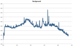
Actually you have a point here. For all spectra I showed, I first did do a blank run (i.e. without sample in place) and used it as a background spectrum (i.e. subtracted it from the signal acquired with the sample. I opened one of the spectrum csv file of the PETG sample with EXCEL and plotted the background signal...:
You can see a peak at 532nm from the reflected laser light making it through the long-pass filters, but clearly also a somewhat prominent peak a 543nm and possibly some broader peaks at higher WLs. This could well be some signal generated in the fiber from the laser as chloderic suspected ! But by using it as a background spectrum, I actually subtract it and it is not visible in the final spectra. I'll try chloderic suggestion to use the input laser without the use of the fiber in the input chain when I have some more time (I can't change the setup as fast as chloderic
") ). Maybe that could result in such clean background signals that he gets instead of the big bump I see in all of my spectra...
). Maybe that could result in such clean background signals that he gets instead of the big bump I see in all of my spectra...Attachments
So far I'm not seeing much I actual believe is raman even using the bw Tek setup and 473.2nm laser. Kind of want to get that working before moving to 532 and ultimately 785nm.
In post #322 of the B&W Tech spectrometer thread, I posted a few raman spectra I managed to obtain with the 473nm laser and unmodified beam splitter (and if I am not mistaken, some other successful results were posted as well, but I could not find them back yet). Check also posts #468 and #478 discussing the setup/method used to acquire these spectra. For me it worked best by putting a small bottle of transparent fluid with a strong raman scatterer (aceton and isopropanol worked best for the liquids I had at hand) almost against the input lens of the beamsplitter. Recently, following the example of chloderic, I found that using a diamond instead of the liquids gave by far the strongest signal I have seen, but I did not try this with the 473nm laser yet.
In general, it was quite simple: (1) specify spectrometer acquisition settings (for instance, longer integration time of 300 ms or higher and nr of averages 20), empty bottle (or no sample) in front of beamsplitter (almost touching the lens) (2) acquire spectrum and set it as background (3) put acetone/isopropanol (or any other strong raman scatterer) in bottle (sample (f.i. diamond)), (4) acquire raman spectrum.
- Joined
- Jun 18, 2012
- Messages
- 1,046
- Points
- 83
I think I didn’t integrate long enough.
The moving microscopy is what I wanted to do using a confocal microscope. The laser being the excitation source with no dye.
The moving microscopy is what I wanted to do using a confocal microscope. The laser being the excitation source with no dye.
I can't keep up with your pace !! Impressive setup :bowdown:! Any idea of the size of the area you are effectively sampling with your setup through the microscope ? Should be quite small, no ?
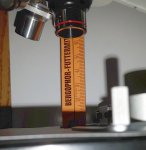
Hi, i think it could be about 5 cm = 2 inch ?
See pic in the attachment.
For the bigger ones above 10 Kg i have the other assembly you can see at the first page and above that (unlimited) .... maybe i will get the part which i called "probe" to run better.
Attachments
Actually I meant to ask how small the laser spot on the sample is. Should be quite small and as such you could detect local changes in chemical composition on a very small scale by moving the sample!
I would estimate the focus to about 0.1 mm, but must move the object of the investigation out of this focus because of the laser beam divergence , so that the rear beam path is as parallel as possible.
Only then can I reach the maximum filter performance of the longpass filter.
- Joined
- Jun 18, 2012
- Messages
- 1,046
- Points
- 83
speaking of longpass filters. Are most of the edge filters 90 or 45 degree? Can't seem to find such a spec. I know you can tune them that way per steve.
I ordered some 785nm diodes. Going to try going for broke on the raman. Just noodling along. Sorry been waiting all thread long to make that pun.
I ordered some 785nm diodes. Going to try going for broke on the raman. Just noodling along. Sorry been waiting all thread long to make that pun.
- Joined
- Jun 25, 2017
- Messages
- 353
- Points
- 63
speaking of longpass filters. Are most of the edge filters 90 or 45 degree? Can't seem to find such a spec. I know you can tune them that way per steve.
I ordered some 785nm diodes. Going to try going for broke on the raman. Just noodling along. Sorry been waiting all thread long to make that pun.
Usually they are for 90 degree, with a angle tunability of 10% of their wavelength (with decreasing steepness of the edge for higher angles. Be aware that there are longpass filters and longpass mirrors. The former have additional filters attached while the latter reflect the shorter wl.
Singlemode
Hello all, some reporting and some questions, especially to the laser specialists around here ! I have been playing around with the setup I described in post #74 above, improving alignment in order to increase the signal. It became quickly a (so far unsuccessful) chase for the origin of the strange lines I get at 537nm and 543nm. But first the findings related to the acquisition of the raman spectra themselves:
- there seems to be no way in my setup to remove the broad background intensity on which the raman peaks are superimposed (see spectra I attached in posts #74 and 78 above). I suspect it is due to fluorescence in the samples themselves, since the background is very sample dependent. This brought background "bump" and the raman peaks seem to scale in a similar way, i.e. the shape of the spectrum does not change very considerably with increasing laser intensity, apart from an overall scaling. The signal to noise is better for intenser laser illumination (as expected). Is this in line with your experiences as well ?
- If re-using the BW TECH hardware, the orange fiber is definitely better to connect the output to the spectrometer. Due to its larger diameter, the signal is definitely better.
- As chloderic mentioned a few posts back, the long pass filters only work well under normal incidence +/- a few degrees. This means that 532nm straylight, that is scattered by off-axis parts of the setup, can still pass through the longpass filter (due to its angle with respect to the optical axis) and possibly make its way to the spectrometer.
- the use of 2 longpass filters in series does not seem to cause any specific problems. The combination blocks almost completely all 532nm light ! For my setup, using only one filter results in a saturated 532nm peak (but it is not causing any problems).
- it seems my resolution for raman lines is mainly driven by the laser monochromacity (or lack of it). I could not resolve some double lines, which are clearly resolved in some spectra I found on the internet acquired with home-made setups.
Now about the strange peaks at 537nm and 543nm: I tried almost everything I can think of to get rid of them, but without success:
- shining the laser directly into the setup, without fiber coupling: no difference (apart from some increase in laser intensity, no impact on the presence of the lines). Therefore, these peaks do not come from the fiber to couple the laser into the setup and I do not seem to have a problem with the fiber over-load mentioned by chloderic in post 76.
- blocking off-axis straylight makes not difference for these peaks. I have tried several simple (i.e. paper) internal baffles in the setup without success. I am more and more convinced the peaks come from on-axis light.
- putting the optical surfaces under a small angle, to avoid multiple reflections between parallel optical surfaces: no difference
- removing one or the other long-pass filter: no difference, except that the peaks become more intense (less blocked by the filters... note that the 543nm peak is beyond the blocking range of the filter !)
- beam dump : shielding the beam dump off from the optical path: no difference.
The only items I did not change are:
- the fiber to the spectrometer, but due to the low intensity of the light in that fiber, I have difficulties to believe that the light would trigger some raman peaks in the fiber itself, especially considering that for the double filter setup, the 532nm peak is almost completely absent).
- the lens on the sample side: I do not have any other suitable lens for that part, but I have difficulties to see what could cause such peaks in that lens (see below for more observations related to these peaks).
- the laser
Therefore my questions:
- any other ideas ?
- for the laser specialists here: could these lines be coming directly from the laser ? It is a simple 532nm dpss laser (no single mode) and I do not use any laser line filter. Can the lines be so far of the center 532nm line ? In addition, I see that these lines are extremely variable in intensity in time: one moment they are completely gone, a few moments later they saturate the spectrometer detector, without any change to the setup ! In the beginning I was puzzled about the fact that the 537nm and 543nm lines were brighter than the 532nm line, until I realised that the long-pass filter was not blocking the 543nm (and less efficient in blocking the 537nm light).
Thanks for any advice !
- Joined
- Sep 20, 2013
- Messages
- 20,284
- Points
- 113
If these peaks are there when no light is allowed into the spectrometer, it must be a problem with the device itself. Best guess would be the CCD. If they are present only when light is applied, they could be second order lines because of misalignment. It is very difficult to troubleshoot a problem without having it in hand to test. I have noticed on some of these spectrometers some peaks that shouldn't be there when no light is applied. These are defects in the spectrometer and if you wish to eliminate them, you will have to figure out which part is causing them. Good luck.
Thanks for the suggestions Paul. The peaks are gone when there is no light on the detector. I also thought about a spectrometer issue (especially because I have seen some hot pixels in them, indeed resulting in "fake" peaks) and made the measurements with 2 of them (both BW TEK spectrometers). Both gave the same result. Furthermore the peaks are wider than one pixel, while the hot pixels I observed were isolated pixels). I have also thought about straylight in the spectrometer itself, but it is difficult to believe this is the case when the 532nm mean peak is almost completely gone. All this seems to indicate it is not a spectrometer problem. Which is why I was wondering if it could be the laser itself ?
- Joined
- Sep 20, 2013
- Messages
- 20,284
- Points
- 113
It is possible, but unlikely. I have some multi-line 532nm lasers, but they are very cheap units. One has four lines and the other six. They are spaced about 4 to 5nm apart, IIRC.
After reading where the peaks are it is possible your laser has extra line. The easiest way to confirm this is with a diffraction grating. You will see a group of three peaks next to one another. I have a sheet of 1000 l/mm that is quite large. If you don't have one, PM me with your address and I'll send you a nice large piece in the mail.
After reading where the peaks are it is possible your laser has extra line. The easiest way to confirm this is with a diffraction grating. You will see a group of three peaks next to one another. I have a sheet of 1000 l/mm that is quite large. If you don't have one, PM me with your address and I'll send you a nice large piece in the mail.
Last edited:
- Joined
- Jun 18, 2012
- Messages
- 1,046
- Points
- 83
As paul said did you check the laser itself for multiple lines? I was discussing this exact issue with a friend who suggested I try to tune the laser with external cavity. Not simple. 543 in a neon line and I think 537 is as well. Do you have a power strip near by? Try a towel over the whole setup
scratch the above.
I put a laser pointer green on the ocean hr2000. you can see as it warms 532 537 543 808 1064. The green lines are reflection sensitive I put a rotator in front and all but the fundamental and pump vanish. The lines are pretty weak but way above the signal from raman so they are significant. A line filter on the green 2-3nm wide will fix it. Try angling the laser a little or putting a microscope slide in front of the laser to act as a window and reflect light off at an angle. It takes very little light to make the problem.
I tried using the sma fiber coupler off the 473nm laser to see if I could eliminate the extra signals. You can eliminate reduce it in the 543 but the 537 is persistent once the laser warms. It seems you would need to take a scan quickly with the laser cold to avoid this. Maybe cool it? I'll toss in fridge.
What else is interesting is the pump 808 is really 810 but the 1064 remains 1064. seems to not move as the pump moves.
BTW the ratio is at least 8000:500 for the fundamental/harmonic 537 and 8000:10 for the 543.
Last edited:
Thanks Paul and kecked ! It seems that I will have to start probing the laser itself, especially considering the lines kecked is observing are exactly at the same position as the ones I am observing. And concerning the intensity ratio: I do observe the lines after the reduction by the long pass filters: the total attenuation of the combined filters at 532nm is several several orders of magnitude, explaining why I can see the 543nm line more intense than the 532nm line. When you mention "reflection sensitive", you mean reflections back into the laser ? That could explain why I see these lines more with reflective samples!
Paul-> thanks for the offer for the grating. I'll first try with the gratings I have in the spectrometers :yh: (both the BW TEK and a converted monochromator with photomultiplier tube). However, for both these spectrometers, I do have a risk for internal straylight and wanted to be sure it is possible to have lines that far off the 532nm... otherwise I would still doubt if it was the laser or the spectrometer...
I'll try to do some tests tonight !
- Joined
- Jun 18, 2012
- Messages
- 1,046
- Points
- 83
yes back reflection. seems I can really unstabilize the laser with back reflection. Maybe try running the laser off a grating or prism. You should be able to with a little extra distance just pick off the 532 line. Not sure how much deflection you get off a grating that close in. but 543 should be far enough to separate out. Hang on and I'll try it. yes you can separate hm on a grating but you need ten oot pth o get 1" separation so no. get and edge filter for 538 and a line/notch fiter or ignore it. cant you background sub the lines?
Last edited: