Welcome to Laser Pointer Forums - discuss green laser pointers, blue laser pointers, and all types of lasers

LPF Donation via Stripe | LPF Donation - Other Methods

Links below open in new window

ArcticMyst Security by Avery

Circuit Help

lazer

0
Joined
Dec 21, 2008
Messages
361
Points
0
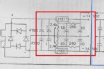
I'm trying to build the circuit attached. I'm having a little bit of trouble with the amp side (red outlined section) though and finding the correct ICs. I looked on Digikey and Mouser but am not sure which to get. The diagram says that I need the TL062. However when I search for that I get a list of several different choices. How do I know which one to use? Also could someone explain what the 1/2 next to the TL062 means? I haven't come across that before as I normally don't use op amps.

This is what you get on Digi-Key by just searching through hole TL062:


Here's the entire circuit:

2m4zp0x.png
 
Last edited:


Joined
Sep 12, 2007
Messages
9,399
Points
113
Y U NO ROTAIT? I HAV SIT LIEK DIS ALL DAI

el-gato-naranjo-del-sabado.png


It means the TL062 is a dual op-amp package. You use half of the chip on the left (bottom?) and half of the chip on the right (top?).

I don't know anything about it to suggest a suitable replacement, but it's not high power and not high speed, judging from the type of circuit it is in. I suspect you could get away with many, many different replacements. Look up the datasheet on google and match a few characteristics on a digikey search.
 
Joined
Nov 7, 2008
Messages
5,725
Points
0
Those TL062 op-amps are actually dual op-amps, so you'd only be using half of it in those parts of the schematic, hence the 1/2 mark. You can most likely get any of the thru-hole varieties you see and be good to go. EDIT: Missed cyparagon's answer.. I was distracted by the cat. What a pain in the neck!

I'd recommend getting your parts on ebay, it's what I do and they are always way cheaper.. sometime you can get nice large assortments for the cost of a few units from mouser or digikey.

Also there are only 2 in that list that are actually thru-hole, so go with one of them. Here's a link :TL062ACP Texas Instruments | 296-12943-5-ND | DigiKey
 
Last edited:

lazer

0
Joined
Dec 21, 2008
Messages
361
Points
0
Y U NO ROTAIT? I HAV SIT LIEK DIS ALL DAI

el-gato-naranjo-del-sabado.png


It means the TL062 is a dual op-amp package. You use half of the chip on the left (bottom?) and half of the chip on the right (top?).

I don't know anything about it to suggest a suitable replacement, but it's not high power and not high speed, judging from the type of circuit it is in. I suspect you could get away with many, many different replacements. Look up the datasheet on google and match a few characteristics on a digikey search.

Sorry about not rotating it. I fixed it.

Didn't notice that only 2 were through hole either. I had hit through hole to filter the results or at least I thought I did. That narrows things down a lot.

That's interesting, I didn't know the 1/2 referred to only using half the chip. All of the results on Digikey look the same to me except 2 had a voltage out spec (20mv). All of them output power though so I don't know why the other wouldn't have a voltage output spec. :thinking:

I guess I'll just pick one and try to find it on ebay. They really all seem to have the same specs except those 2 weird ones that had a voltage output listed. It's just weird that they would all appear to be the same but have different model names/numbers.

One other question: From the transformer section there are 2 14volt outputs (+ and -) that say to op-amps. However, if you go look at the amplifier section around all the op amps there is no marking that I can see for where to actually hook up the 14 volt outputs to the op-amps. There are 2 places for the positive and negative 9v leads for the microphone but nothing for the 14v. Can one of you explain where you think the 14v is supposed to go in the amplifier section?
 
Last edited:
Joined
Sep 12, 2007
Messages
9,399
Points
113
The voltage rails of op-amps are often left out for simplicity. The +14V goes to the positive voltage input, and the -14V goes to the negative voltage input. According to the datasheet, that's pins 8 and 4 respectively.
 

lazer

0
Joined
Dec 21, 2008
Messages
361
Points
0
The voltage rails of op-amps are often left out for simplicity. The +14V goes to the positive voltage input, and the -14V goes to the negative voltage input. According to the datasheet, that's pins 8 and 4 respectively.

So that's how it works. Thank you! I couldn't find that anywhere. :D I'll order the parts later this week and get to building it. I may have some more questions later if something doesn't work but I should be good for now. :)

I'm going to try and use a computer power supply in place of the transformer portion to simplify and speed the building process up. I'll still use the 9v battery for the microphone but the 14v dc for the op amps I am going to try and get from the computer power supply.
 
Last edited:
Joined
Sep 12, 2007
Messages
9,399
Points
113
They have +12V at up to several amps, and -12V at up to several hundred mA. This is probably close enough, but they're large and have several watts of standby power draw. You might want to use a couple wall warts instead.
 
Last edited:

lazer

0
Joined
Dec 21, 2008
Messages
361
Points
0
They have +12V at up to several amps, and -12V at up to several hundred mA. This is probably close enough, but they're large and have several watts of standby power draw. You might want to use a couple wall warts instead.

Drawing large amounts of stand by power won't be an issue because the whole thing will just be sitting on a table. I'm not too concerned with efficiency or power usage because it's not intended to be portable. I'll try the wall warts though. Those sound like a better idea. I completely forgot to consider those rather than the computer power supply. That was just the first thing that came to mind.

I only see axiz modules in that link. Are there wall warts there too?

How would I know which wall wart to get current wise? I'm not sure how much current is required to drive the op-amps and whole amplifier section (minus microphone since that has it's own 9v battery). Don't wall warts only give around an amp. Do you think a 1-1.5 amp 14v wall wart would be good enough or something a little smaller?

Also would the wallwart still work if I needed to ground the circuit? There is a ground output pin between the +14v and -14v on the transformer section. Most wall warts don't have a ground pin right (I'm assuming that the ground pin is the 3rd middle pin on outlet connections)? Wall warts only have the standard 2 pin connections to the wall. Would I just use the negative pin on the wall wart as both the ground and -14v?
 
Last edited:
Joined
Sep 12, 2007
Messages
9,399
Points
113
Sorry, wrong link. Try this instead.

1A should be more than enough, and 1A adapters are pretty much the same price as lower currents. 12V is a standard voltage, 14V isn't. 12V is close enough.

Yes, virtually all wall adapters have a floating output (no ground) so they can be used in series for +/- 12V.
 

lazer

0
Joined
Dec 21, 2008
Messages
361
Points
0
So just to be clear for all the points in the circuit that have the ground symbol, I just hook those up to the - output of the wallwart?

Yeah idk why this circuit asks for 14v instead of 12v. I'll try 12v, I really don't think it will matter enough to cause problems.
 
Joined
Sep 12, 2007
Messages
9,399
Points
113
No, one adapter will be the positive rail. That means the positive output of the adapter will be the positive of your circuit, and the negative output of the adapter will be the ground of your circuit.

Similarly, the other adapter will be the negative rail. That means the negative output of the adapter will be the negative of your circuit, and the positive output of the adapter will be the ground of your circuit.
 
Joined
Nov 7, 2008
Messages
5,725
Points
0
Depending on power involved it seems like a properly chosen DC-DC converter would be ideal here.. 9-36VDC in, +/-12VDC out, sources a decent amount of current. Both rails from one 9-36VDC input: VYB10W-Q24-D12-T CUI Inc | 102-2310-ND | DigiKey

On ebay (much cheaper, slightly lower power handling, higher input voltage): http://www.ebay.com/itm/DC-DC-Conve...062?pt=LH_DefaultDomain_0&hash=item23171ff68e

Lower power, 5VDC in +/- 15VDC out: http://www.ebay.com/itm/DC-DC-conve...259?pt=LH_DefaultDomain_0&hash=item2572c68ecb

Shouldn't really require much power for your op-amps there..

Never overly cheap, but they simplify things a bit..
 
Last edited:
Joined
Oct 26, 2007
Messages
5,438
Points
83
What're you using the circuit for? If it's audio-related, which is looks like the original circuit is, you'll probably still want to build the "transformer compartment" part of the circuit after the rectifier (red-highlighted section):

attachment.php


It'll ensure that the power to your op-amps and everything else is nice and clean. This is even if you're going to use a wall-wart, DC/DC converter, or a computer PSU, which can still be somewhat noisy. Just connect DC power + to the to the top input the - to the bottom, and ground to the center tap (assuming a +/- supply).
 

Attachments

  • clean_power.jpg
    clean_power.jpg
    56 KB · Views: 1,226
Joined
Nov 7, 2008
Messages
5,725
Points
0
Didn't even look at the schematic myself lol.. that's all you need right there. Provides clean +/-14VDC.
 

lazer

0
Joined
Dec 21, 2008
Messages
361
Points
0
No, one adapter will be the positive rail. That means the positive output of the adapter will be the positive of your circuit, and the negative output of the adapter will be the ground of your circuit.

Similarly, the other adapter will be the negative rail. That means the negative output of the adapter will be the negative of your circuit, and the positive output of the adapter will be the ground of your circuit.

So does that mean I connect both grounds of the adapters together so there is are 3 total outputs (ground, +, and -)? Sorry if this is dumb question. I found this article: How to Build a Robot Tutorial - Society of Robots
Is that kind of what you are explaining? I haven't worked with positive and negative rails before.

Depending on power involved it seems like a properly chosen DC-DC converter would be ideal here.. 9-36VDC in, +/-12VDC out, sources a decent amount of current. Both rails from one 9-36VDC input: VYB10W-Q24-D12-T CUI Inc | 102-2310-ND | DigiKey

On ebay (much cheaper, slightly lower power handling, higher input voltage): DC/DC Converter, 7 Watts Tri-Mag 48 VDC Input, +12/-12 Dual VDC Out , Isolated | eBay

Lower power, 5VDC in +/- 15VDC out: DC/DC converter 2W isolated 5V IN +/-15V dual out.1pcs | eBay

Shouldn't really require much power for your op-amps there..

Never overly cheap, but they simplify things a bit..

A DC-DC converter wouldn't work though, right, if I want to be able to plug it into the wall with AC power? I would still need to convert it to DC before it goes to the DC-DC converter. Wouldn't it be simpler to just use a wallwart?

What're you using the circuit for? If it's audio-related, which is looks like the original circuit is, you'll probably still want to build the "transformer compartment" part of the circuit after the rectifier (red-highlighted section):

attachment.php


It'll ensure that the power to your op-amps and everything else is nice and clean. This is even if you're going to use a wall-wart, DC/DC converter, or a computer PSU, which can still be somewhat noisy. Just connect DC power + to the to the top input the - to the bottom, and ground to the center tap (assuming a +/- supply).

It is audio related. It's a circuit to record the songs sung by drosophila (fruit flies). It's for an experiment being done at the college lab I am working in. The microphone is smaller than a pin head and needs an amplifier to amplify the signal it outputs enough for the lab equipment to record and pick it up.

I'll be sure to include that section. I thought the wallwart would be clean enough. Guess not. Thanks for pointing that out. :)

Didn't even look at the schematic myself lol.. that's all you need right there. Provides clean +/-14VDC.

Lol So no dc-dc converter? Just a wallwart and the noise filter section of the transformer compartment?


For the op amps in the amplifier section, only 3 pins are used on each one but their are 8 pins per chip.

Example: this is the TL062's pin out sheet

11vp4cn.jpg


Do I use pins 1, 3, and 4? With 4 being Vcc-, ground? All of the other pins are unused and left by themselves? It is a dual amp but the schematic says that only half will be used.

On the LM387 it says that the extra inputs should be shunted to ground, does that only apply to that chip and not the others like the TL062?
 
Joined
Nov 7, 2008
Messages
5,725
Points
0
A DC-DC converter wouldn't work though, right, if I want to be able to plug it into the wall with AC power? I would still need to convert it to DC before it goes to the DC-DC converter. Wouldn't it be simpler to just use a wallwart?

A DC-DC converter will definitely work ALONG WITH a single wall wart (or other power supply). You just have to supply whatever the input voltage is on the DC-DC converter you end up using. For example, the second ebay link in my post takes 5VDC in (from a single 5VDC wall wart or whatever) and gives you +/- 15VDC out from three terminals: one +, one -, and one GND. But you don't really need it if you build the red circled portion of your schematic that Badger pointed out.

Lol So no dc-dc converter? Just a wallwart and the noise filter section of the transformer compartment?

Correct, you do not need a DC-DC converter OR more than a single wall wart if you build that section of your schematic. That section performs the same function as a wall-wart and DC-DC converter or two wall-warts. Once built, that section rectifies AC input and provides +/-14VDC, again via three terminals: One +, one -, and one GND.
 
Last edited:


Top