Hiemal
0
- Joined
- Dec 27, 2011
- Messages
- 1,443
- Points
- 63
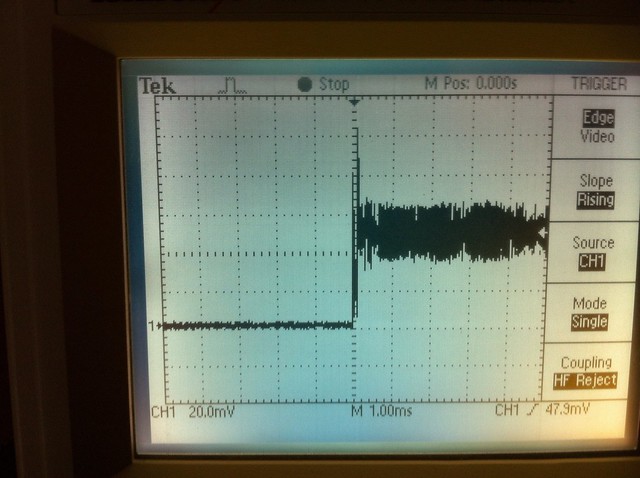
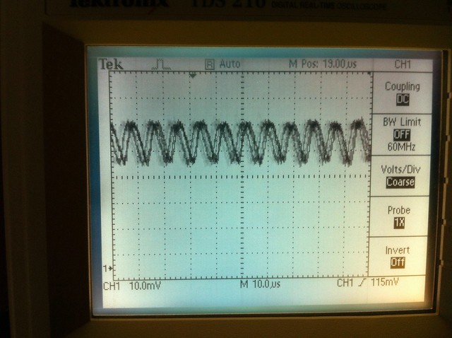
The ground will always STAY ground though, so the mosfet will always be ON.
The IC won't/shouldn't have any effect on how the mosfet is on or off. It's like, taking a mosfet, and then taking a switch, putting it in series with the mosfet, and switching the switch really really quickly. The mosfet doesn't care, and shouldn't care what happens after it, because it doesn't. There's no reason for the MOSFET to be switching on and off, because the gate is held to ground.
The IC won't/shouldn't have any effect on how the mosfet is on or off. It's like, taking a mosfet, and then taking a switch, putting it in series with the mosfet, and switching the switch really really quickly. The mosfet doesn't care, and shouldn't care what happens after it, because it doesn't. There's no reason for the MOSFET to be switching on and off, because the gate is held to ground.