Blord
0
- Joined
- Dec 24, 2007
- Messages
- 5,356
- Points
- 0
You surely how to produce them en masse ! 


Wow, nice.
Wow, nice.
That thing almost looks smaller than my Trustfire XP-E F23, and maybe lighter*. :undecided:
Check the LPM vid:
*will weigh later today
Yeah its way smaller then the F23:
Here is a comparison video i did along time ago of pretty much most of the smallest 10440 that are known around the forum:
Skip to 3 Minutes:
There is No Comparison. You cant get any smaller unless you shorten it lengthwise.
The 14500 version that i have of this host is pretty much the same size of the F-23.:crackup:
Lol, it is SUBSTANTIALLY smaller and lighter. Different ballpark completely.
I know everyone was real jazzed about adding OVP, but I'm really having an issue with grafting it onto this board the way we have (instead of creating a second fork that gets independently tested). Specifically, I don't understand why R4 isn't going to screw up our FB pin's reading.
Two issues I have:
1) We're placing R4 between (R1,R2) and (GND). So at the very least, isn't this going to throw off current setting?
2) The layout also creates a much longer path between the FB and the GND pins. In most layout tips I've read, this route is usually minimize. Here we're going from the GND side of the current setting resistors, back to the GND through-hold, onto the other side of the board, over to the vias under the IC, back up, and to the GND pin. This seems like a long route.
I'm sure I'm missing something here because I know a lot of eyes have cracked away at this. But it just doesn't seem right to me. I don't have the actual OVP board in front of me, so I don't know any of this to be an issue. But conceptually, this is bugging me.
Are we just counting on R4 not to drop any (much) voltage, since the mass of current won't be flowing over it?
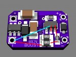
EDIT: Here's a render, with my understanding of the new FB route on it. (Red for top of board, Cyan for bottom)

well on a brighter note, I would like to say good luck to everyone trying to build/sell these boost drivers, and also to everyone who is trying to learn more about all there different driver options.
I'm finding that practically speaking, they need heatsinking above 1A. I'm also finding that I don't really like them above 1.2A, even though I've had some luck at 1.4A. It definitely seems like the 1.2 to 1.4A range is the range in which you need some luck. I wouldn't have thought there would be variability from driver to driver, but I've had some 1.4A set drivers that just can't do it even when heatsinked. I also suspect that at 1.4A, they'll start to REALLY struggle when supply voltage sags.