Welcome to Laser Pointer Forums - discuss green laser pointers, blue laser pointers, and all types of lasers

Buy Site Supporter Role (remove some ads) | LPF Donations

Links below open in new window

FrozenGate by Avery

Cylindrical Lens Advanced Test - Bed ( CLAT-B)

Joined
Feb 25, 2010
Messages
1,643
Points
113
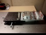
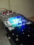
Hello All...This is a little side project to more accurately determine the optimal separation distance between two (2) Cylindrical lenses.

As you likely know, Cylindrical lenses greatly reduce the spread on our newer high power multi-element Laser diodes. They do their optical Voodoo by expanding the slow axis of an asymmetric laser diode beam....to match that of the fast axis....Read...Beam = ( Close )Dot...not bar.

Who cares !! What is important is that the separation distance between the lenses is critical to the optics doing a good job at shaping /hammering the beam into something....almost square. A plus/minus of .05mm has impact on the effectiveness of the Cylindrical Lens Corrective optics.

SOooo...I wanted to assemble a ...Cylindrical Lens Advanced Test - Bed...( CLAT-B)...to really determine this distance closely !!

This separation distance can be determined...by...pushing the lenses...Back...and forth....dozens on times !!!!....such a PITA though !!!

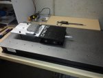
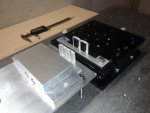
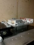
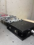
I had a 1' x 2' x 2" thick... Lasershop - Optical Breadboard from a long ago project....and a Newport Model 400 XY Translation stage ( Doesn't everybody )....so I decided it was time to play like the professionals do....and test the Cylindrical Lens with great accuracy in positioning.

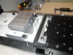
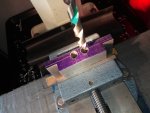
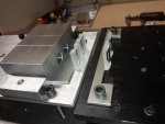
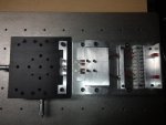
I machined and assembled a LD mount to accept two (2) 12 x 30 CU modules as the pic shows. The LD's will be secured in the Aluminum mount.
This test unit has two separate areas..independent of each other....the Mount platform which holds the LD Mount...and the Translation stage. The XY Translation stage has two micrometer set units that set the stage position....left/right....back/forth.

SOooo....the LD's are locked into position. The First Cylindrical lens ( Plano Concave) is slid into position...against the bar stop directly in front of the LD mounts...atop the Mount platform.

The Second lens ( Plano Convex) is then positioned atop the Translation stage...against the U-Channel Bar stop.
The Plano Convex lens is then adjusted with the micrometer set unit....back and forth. The optimal separation distance is determined by observing the Far Field beam geometry. When the smallest geometry is noted....the optimal separation distance between the lenses has been found !!

I built the unit as a dual LD holder because I intend to use this CLAT-B as a test area to verify the optical design of the Cyan Cannon ll. See the drawing of the Cyan Cannon ll attached.

Anyway....thought a few of you would enjoy seeing this little sortie into a more advanced test jig !! Optics are FUN !! :san::san::san:

Note: The CLAT-B is not quite down....still must fix the Diode mount to the Mount platform and install the LD modules...will post pics when complete !
 

Attachments

  • CLAT B 2.jpg
    CLAT B 2.jpg
    355.7 KB · Views: 245
  • CLAT B 3.jpg
    CLAT B 3.jpg
    388.6 KB · Views: 233
  • CLAT B 1.jpg
    CLAT B 1.jpg
    404.2 KB · Views: 195
  • CLAT B 4.jpg
    CLAT B 4.jpg
    356.3 KB · Views: 255
  • CLAT B 5.jpg
    CLAT B 5.jpg
    361.6 KB · Views: 284
  • Cyan Cannon II with full Acrylic Shroud V4.JPG
    Cyan Cannon II with full Acrylic Shroud V4.JPG
    38.7 KB · Views: 178
Last edited:


Nice job, but how are you going to do transfer these off the translation stage?

Well....This will determine what the optimal separation distance is only. One method to record the exact separation distance would be to remove the lenses when the optimal Far Field geometry is achieved...and measure, with digital calipers the distance between the stop bars.

Then ....subtract the lens thickness of the Plano Concave lens....and this will give the separation lens to lens distance that one must place the optics within the build !

This just gives us the target distance to duplicate only.

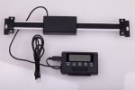
OR....I suppose a simple, inexpensive, single axis DRO could be mounted between the Translation stage and the LD Mount platform....See this link...

12" Digital Readout Read Out DRO w Remote LCD for Bridgeport Mill Lathes | eBay

Dunno ??? I have not decided yet. Only $ 36 USD to try it !!

:whistle::whistle::whistle: :thinking::thinking::thinking: See pic of DRO.
 

Attachments

  • Simple single axis DRO.jpg
    Simple single axis DRO.jpg
    175.9 KB · Views: 202
Hi Rob!
Damn I cannot rep You again :mad:
Only a question: every multimode diode has a different beam profile, even between two diodes of the same family. This means that when You found a correct distance between the two lenses with a certain LD, the same distance could be not suitable for another LD. It is right?

Hmmmmmm:undecided::undecided::undecided:

Yes....I am sure no two (2) laser diodes are exactly alike....even the exact same model diode.....And.....I am sure that their are variations in Optical lens manufacture.

But....the big question is....in reality....how much variation ?????
And an even bigger question....will we be able to determine the difference....with just our eyes !!!

Now....If I had a Beam Profile machine....I am sure that with that ultra precise
resolution....we would see variation....between LD's.....and with lenses.

It just boils down to how close you look at things !!! What resolution factor do you use !!! ???

I want to cobble together an inexpensive Beam Profile unit....using CCD imaging....That is a future project !!!

For now...I only have digital calipers...and my eyeballs !!!

Funny thing though....with these power levels....One can now ablate/burn the Far Field target....and then....just measure the burn outline !!! Just do not set the Far Field Target surface on fire !!!! HAHAHA

I would add that....I think it is a good idea....to set the lens to lens separation distance...for each Laser Diode that you intend to optically correct.

The measurements determined by the CLAT-B.....will "just get you in the ball park "....then....you go from there. At least....that is the way I will do my builds in the future !!!

A set-up such as the CLAT-B is not demanded to get one in the ball park....but...it will likely save time !!! Prior to this...I would just push the lenses back and forth....This works....but...using the CLAT-B will be a more efficient method to determine the optimal distance !!:beer::beer::beer:

Thanks for the kind words !!!.....Now...back to the Lab !!!
 

Attachments

  • DocBrown  endorsement  Base No text with frame.jpg
    DocBrown endorsement Base No text with frame.jpg
    80.8 KB · Views: 91
Cool stuff thanks for sharing!

Looking forward to your results and beam pics etc...

I would also be interested in the power loss at final output after the lens sets vs a G-lens...
 
Cool stuff thanks for sharing!

Looking forward to your results and beam pics etc...

I would also be interested in the power loss at final output after the lens sets vs a G-lens...

Thanx for the feedback !!

Will post when complete. I have measured these lenses B4....and loss is negligible....as in 98.2% transmissivity. :beer::beer::beer:
 
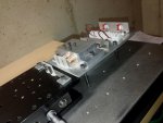
Some progress on the CLAT-B See pics....ready for first light with the
NUBM07E and NUGMO1T....just a little more wiring ta do!! Will fire'em up tomorrow.

Lazereer drivers are clamped down with a Ally square bar directly behind the LD mount.....which presses them down to the Mount platform. This method provides a temporary lock-down...and a good thermal path to dump the driver heat.

All this is primarly for experiments to establish the optical path to be used in the Cyan Cannon ll build !!....but of course... this unit will come in handy for future optical corrected builds !! Will post some operational pics later ... :tinfoil::tinfoil::tinfoil:
 

Attachments

  • CLAT B close to LD on 2.jpg
    CLAT B close to LD on 2.jpg
    386.7 KB · Views: 142
  • CLAT B close to LD on 4.jpg
    CLAT B close to LD on 4.jpg
    369.9 KB · Views: 147
  • CLAT B close to LD on 3.jpg
    CLAT B close to LD on 3.jpg
    334.6 KB · Views: 107
  • CLAT B close to LD on 1.jpg
    CLAT B close to LD on 1.jpg
    198.7 KB · Views: 59
Last edited:
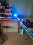
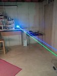
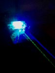
Well....We have first light with the CLAT B unit !!!!! Sky Blue and Forrest Green Photons are the order of the Day !!!

Installed are ;

NUBM07E in copper module with solid back + SXD-V3 set to 4.5A with 3-4 second ramp up + G Lens

NUGM01T in copper module with solid back + SXD-V3 set to 2.15A with 3-4 second ramp up + G lens

This... I believe.... is the first applications of 6X Cylindrical Lenses to the NUGM01T diode.....Well....the results are very, very good....a nice, tight spot at 25 ' ( 7.62M)....about 5.1 mm in diameter !!

The Blue is not quite as tight as the Green....but close !!!

These two (2) LD's will combine nicely into a combined overlay of Cyan Beamage !!!

On the CLAT-B unit...I have the NUBM07E.....installed right next to the NUGT01T....at 18.80mm center line separation....just as it will be on the CC ll build. This spacing arrangement was selected to do optical experiments ....which will guide the construction of the Cyan Cannon ll build.

As of this writing....I believe that the optical set-up for the CC ll will employ only one set of 6X Cylindrical lenses. From experimenting... I have concluded that the separation distance demanded between the Cylindrical Plano convex and Plano concave is equal....for both LD's

SOoooo....that means....I can combine the beams first....and then correct the combined beams with just one set of Cylindrical Lenses. How fortunate !!! Makes the build less complicated and less expensive.....See the Pic.

For those of you considering using Cylindrical Lenses to tighten up your beams....and to mostly eliminate the hated " BAR".....this is the way ta do it !!!

Stay tuned for further Optical Voodoo ....Beam combining....over at the Cyan Cannon ll build thread !!

:san::san::san: See the attached pics !!
 

Attachments

  • CLAT B OP 1.jpg
    CLAT B OP 1.jpg
    239.8 KB · Views: 156
  • CLAT B OP 2.jpg
    CLAT B OP 2.jpg
    248.3 KB · Views: 144
  • CLAT B OP 3.jpg
    CLAT B OP 3.jpg
    217.6 KB · Views: 147
  • CLAT B OP 4.jpg
    CLAT B OP 4.jpg
    157.3 KB · Views: 129
  • CLAT B OP 7.jpg
    CLAT B OP 7.jpg
    123.9 KB · Views: 126
  • Cyan Cannon II HSOP 7 Single  for printing CL.JPG
    Cyan Cannon II HSOP 7 Single for printing CL.JPG
    167.7 KB · Views: 153
Last edited:
@CDBeam777 No wonder you don't have much time. Wow, unbelievable. This will be something when you perfect it!
 
@CDBeam777 No wonder you don't have much time. Wow, unbelievable. This will be something when you perfect it!

Yikes...You shame me into working some on the Cyan Cannon ll project.....on the side track for a while as I do a custome job for another member !!!!

Just not enough time !!!!!!!!!!!!!:D:D:D
 
Cyan Cannon ll! December?

Maybe !!!

See the build thread....new design !!! "new and improved" ....hahahaha

This changes the size Acrylic tube I need....oh....yikes....and I forgot....I will need two (2) SBX boost drivers now !!!...because I will be using a single cell
32650 LiPo....

As " MArvin the MArtin" sez....." Delays....Delays " !!!


Back
Top