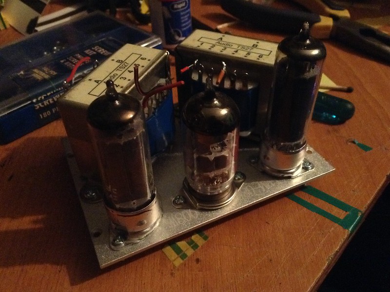
Awesome! I'm jealous of you for having a professional looking build underway from "scrap". I'm stuck using an old recycled radioshack plastic abs project box as a mounting surface. I had to order in some four pin bottom mount sockets, but got them cheap domestically on eBay for a change. Yours look way nicer quality than the ones I ordered though.
Where'd ya find the awesome matching plate trafos?
I did some experimenting with negative feedback on my dual triode amp today. While it worked well to suppress noise, the loss in gain was quite noticeable. I guess that's why they didn't really employ it for triodes, but rather tetrodes and pentodes. I also experimented with positive feedback for additional gain, but it was pretty marginal.
Data for others to benefit from: Negative Feedback is easiest to implement via a series resistor between the output valve's audio-pickoff transformer's secondary and the first stage valve's cathode. One leg of the transformer secondary will yield negative feedback, while the other will yield positive feedback. Adding L and or C will affect the frequency response of the NFB loop to shape the output sound.
Negative Feedback + less series resistance = less gain, stronger effect of sound shaping.
Negative Feedback + more series resistance = more gain retained, weaker effect of sound shaping.
Adding a series capacitor forms a high-pass filter in the negative loop, which has a net Low-Pass effect on the sound.
Adding a series inductor forms a low-pass filter in the negative loop, which has a net High-Pass effect on the sound.
Positive feedback loops are more intuitive; more resistance = less additional gain. Series L and C values do not have "inverse of normal" effects on the sound. Depending upon the bias points used and the series resistances chosen positive feedback can introduce a lot of distortion as the tube goes into full conduction and begins to flat-top the signal.
I tried many, many values and ranges of R and C for the NFB loop but couldn't find a sweet point of gain vs low-pass effect that made the output sound better than without the NFB loop. I'm using a higher frequency range small speaker without an enclosure so there is a large inherent high-pass effect. Despite achieving significant results in low-pass filtering I still couldn't balance the sound profile. It would go from "muddy AND tinny" to "thin" with no sweet spot in between. I tried 0-500kOhms linear taper and 1pF to 1uF in x10 increments. The best altered sound I achieved was with a combination of 2.2kOhms + 80nF/47nF (one was better at one song, another for another) and a Positive feedback loop with only a series junkbox mystery inductor somewhere on the order of 100-100uH. The PFB enhanced the bass response while the NFB reduced the treble. Unfortunately nothing seemed to reduce the 60Hz hum (I suspect I'd need a notch filter) or the real high frequencies, above about 7kHz, which was very strange. The low pass effect of the NFB loop should have rolled off everything over the 3dB frequencies but really it just had the effect of a negative Gaussian curve. The result was upper-midrange scooping with linear reduction in bass/treble just due to loss of overall gain. Not sure why that happened.
In the end I decided to stick with the 1920's topology of no feedback and just deal with the frequency response by other means.
I tried briefly to rectify and filter the heater lines to nix the hum but had no luck. Oddly enough the heater wouldn't glow under DC, even though they do from my bench supply. This power supply (for the amp) uses an odd means of grid bias by having the heaters (and consequently the cathodes) at about 23V relative to true ground and then grounding the grids. This makes it difficult to alter without screwing things up. I suspect that due to the large negative bias and zero isolation something ran afoul (hard to believe with 1 diode and 1 cap!) in my wiring. I had rectified and filtered an unused filament line before but it was the 5V line for the 227 tube I'm not using, and that one's heater isn't held so far negative to ground. Plus, there was a layer of isolation because of the impedance matching transformer used between the silicon preamp and the grid of the 226.
I'd certainly consider implementing NFB again if I can get a proper sharp slope 60Hz notch filter figured out.


