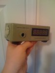
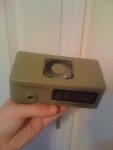
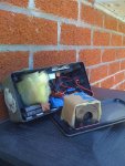
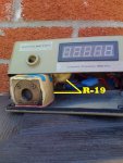
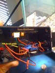
Here are those pics you guys asked for, I insulated the pile with R-19 insulation, Then I isolated the pile from the rest of the components with some more R-19 so that it does not recieve any air flow just the electrical components are cooled! I hope this helped you understand my logic a little bit better.
-Sarge
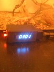
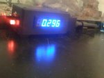
Hey DM.... you got a small problem....:cryyy:
Speaking only for accuracy's sake....................
The principle of a Thermal head is to have a non heat dissipating
surface (where the laser hits) on one side of the Thermocouple
circuit and a Large Thermal Mass (the large Black aluminum Block)
to dissipate (into the surrounding ambient air) any heat transferred
to it by conduction from the Active Area of the Thermopile sensor.
By insulating and putting your Thermopile in a Box you are defeating
the heat transfer/dissipation design of the Thermopile... IMO
Since your Head is insulated...if you are taking multiple readings of..
let's say... 1 Watt Lasers... the Heat absorbed by the Sensor and
conducted to the Thermal Mass will not get dissipated to the
surrounding air and will heat up the mass more and more...
It is the difference of temperature of the Active Area and the Thermal
Mass that translates to an accurate Power Reading.... and that is the
way the head was originally calibrated by OPHIR...
[
EDIT]
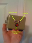
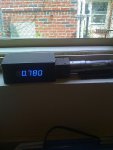
BTW.... All of the Lite's electronics and head combined only draw about
70mA.... Where is the heat coming from that you need a fan to keep
it cool....:thinking:
My Lite runs off a 9Volt rechargeable Battery...
Jerry