Well, I have a few empty projectors now, and I've been experimenting to see what I can find, and if there is any way I can get them to power up without any LED's, and wihtout having to use bulky, hot resistors.
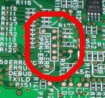
I have found the LED and LD's are both controlled from 1 PCB. This PCB gets power right from the PSU, and only has 1 ribbon cable between it and the main PCB. So, the error signals must be travelling through this ribbon cable, so my aim is to try and find it, and trick it into thinking its OK. I have taken some closeup pics. Casio were nice enough to label pretty much ALL the connectors, and even supply a plethora of diagnostic pins, so maybe someone can help interpret anything that could be of help!


We know the projector shuts off with both overtemp and missing diode warnings. So there has to be at least 2 error lines here. Worst case it uses serial communications for error reportings.
Cheers,
Dan
I have found the LED and LD's are both controlled from 1 PCB. This PCB gets power right from the PSU, and only has 1 ribbon cable between it and the main PCB. So, the error signals must be travelling through this ribbon cable, so my aim is to try and find it, and trick it into thinking its OK. I have taken some closeup pics. Casio were nice enough to label pretty much ALL the connectors, and even supply a plethora of diagnostic pins, so maybe someone can help interpret anything that could be of help!
We know the projector shuts off with both overtemp and missing diode warnings. So there has to be at least 2 error lines here. Worst case it uses serial communications for error reportings.
Cheers,
Dan


")
")