Welcome to Laser Pointer Forums - discuss green laser pointers, blue laser pointers, and all types of lasers

LPF Donation via Stripe | LPF Donation - Other Methods

Links below open in new window

ArcticMyst Security by Avery

Trying to adjust output. Help!!

Joined
Jan 8, 2013
Messages
138
Points
18
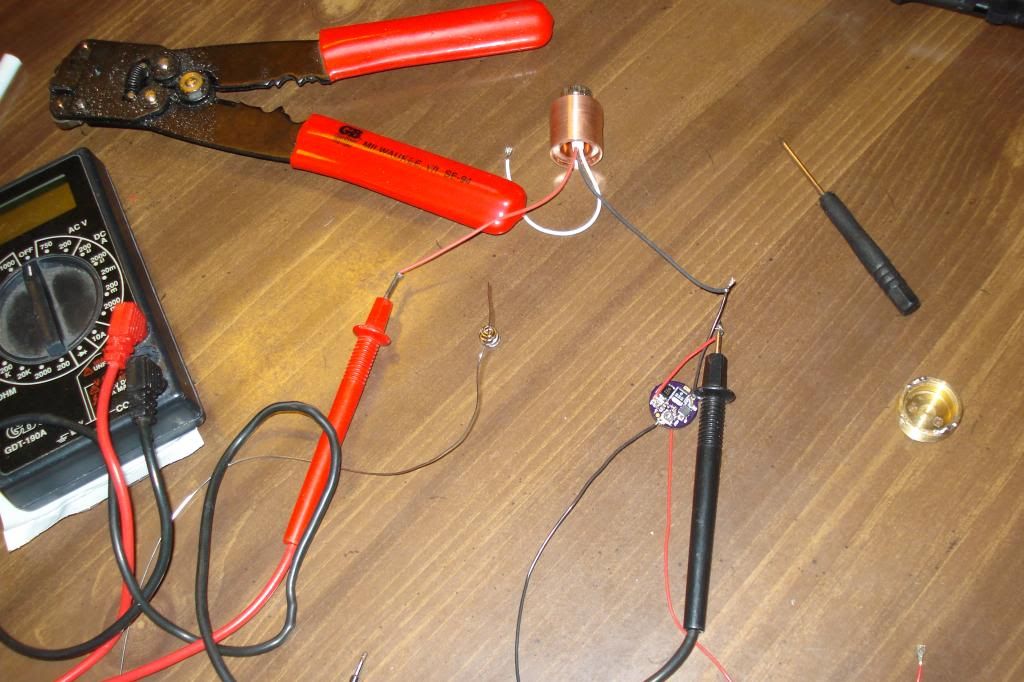
I am trying to set my current for my M-140. Im using an x-boost driver, connected to the diode on the - side, on the + side i have my DMM between the doide and the driver. I have the driver wired to a RCR123a battery.

So far, I have only seen it get past 1.0 once on the DMM, and I have turned the pot both ways several times and it doesnt seem to want to go any higher (it fluctuates down to about .4a at the lowest). Whats the problem here?

FWIW, the DMM red cord is plugged into the 10A port, and Im using in on the 10A option...

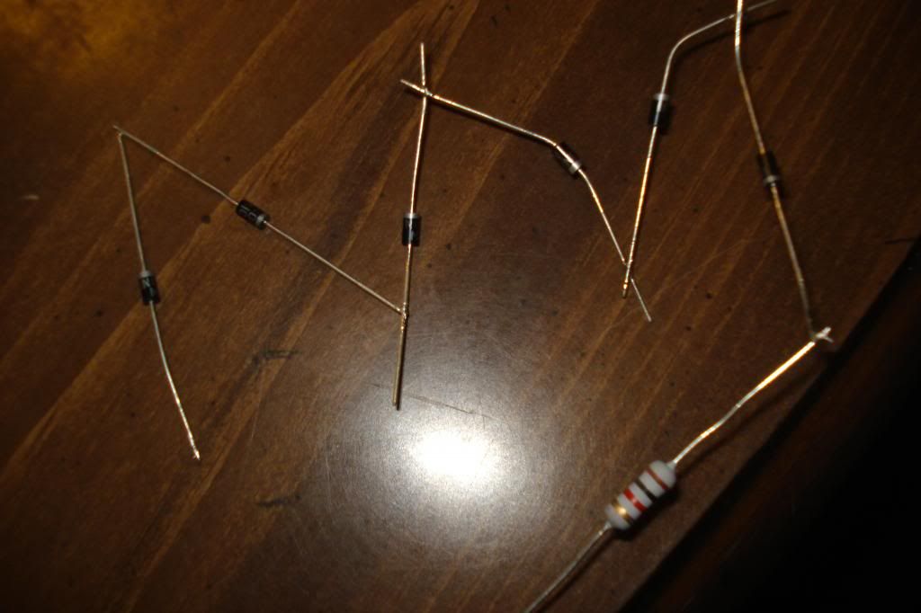
Edit: Here are some pictures of how I have it set up. I also have a test load I built, but straight out of the gate it was giving me readings I didnt find consistant with the driver specs, so I figured it was wrong. It was saying like 2.6A right when i turned it on, and on cajun lasers it says the max is 2.2A.

DSC02200_zps6fd4a861.jpg


Here is the test load, its 6 diodes N4001, and a 1-kohm, 1 watt resistor.
DSC02201_zps6d1f0f78.jpg
 
Last edited:


Joined
Jan 8, 2013
Messages
138
Points
18
I charged my RCR123a battery fully, and have tried setting this again. No matter how many turns on the pot, turning it counter clockwise, it jumps up to 1.13, and gradually tapers off. Whats going on? Why wont this thing turn up?

I really need help. I dont want to break anything, and have been searching for an answer all day now on here, and have not found any useful information. I just turned the pot 3 complete turns, still says 1.13a on DMM

Edit:
Now I finally got my 18650 battery charged. I have hooked it up, and it gives me a reading of 1.58 on the DMM, but thats at the same setting that the RCR123a was giving 1.13 at, and I have still adjusted the pot, what seems like a million turns, and it doesnt go anywhere.... every once in a while it'll be at like .3a, but then i just turn it a tiny tiny bit and it goes back to 1.58a and stays there for the next million turns (until it goes to .3a again, like i said, every once in a while)
 
Last edited:
Joined
May 25, 2010
Messages
3,655
Points
0
Hello,

I dont think you understand what your doing or understand the specs that well. Id be happy to help though.:)

If you where getting a reading of 2.6A then you where testing the currant that it was pulling from your cell not the currant going to the diode.

THe 2.2A that is listed on the site is the MAX the driver can Supply to your diode. HOWEVER the Max output for that version is 1.9A so 1.9A is the max you will get if you have the driver set correctly.

Next is your setup is very Loosely put together. I would not be surprised that at some point the driver got disconnected and it died. But lets be positive and hope it still works.


I test EVERY driver before i ship out. (EVERY ONE) So it is Nearly impossible to have a DOA. I almost want to say impossible.
Ive shown my Driver test setup several times on this forum and everyone knows i test every driver before they go out for sale.

So my best guess is there is something you are not doing correctly or there is something in your setup not working correctly.

First thing first a RCR123A will not be able to supply enough currant to power 1.9A. NO driver can do this and maintain it safely. Its too much currant.

The testload you made is only good for ~ 1A if that. That resistor you are using probably can only take ~ 1A before it over heats and gets damaged.

Using an 18650 AW Cell should have no problem suppling enough however when you have it running through that loose setup and all that wiring then i dont think it will perform correctly.

Even though your DMM is rated for 10A your Leads are Not.! Those DMM leads are very cheap and for 1.9A at 4.2V you will be pulling ~ 3A..

With your setup being so loose and all the long wiring this is what is causing your issue.

Not to mention you dont have the driver heatsinked.

Finally You Have 6 diodes on your testload. NO wonder your not getting full currant.!

6 diodes will give you a load of over 6V probably 7V. Thats not possible to be accomplished.

You need to ONLY Use 3-4 diodes for your testload. That will give you ~5V at 1.9A and pull ~ 3A from your cell if its at 4V or more.


So here is what i recommend you do.

First thing first is Please solder your wired together to your test setup. Make everything nice and clean setup and tight.

Next use 3-4 diodes instead of 6 for your testload for 1.9A.

Finally have your 18650 cell as close to the driver Voltage input so that it doesn't have to run through so much wire to deliver the power.

Do not turn the pot all crazy. Turn it Slowly.

That right there should solve your problems.:)
 
Last edited:

DTR

0
Joined
Jun 24, 2010
Messages
5,684
Points
113
Also this right here is one of the easiest ways to kill the diode and possibley the driver along with it.

You always want a solid soldered connection between the diode and driver. Having the multimeter in series with the output of the driver yes it can give you the current going to the diode but if you get even the briefest intermittent contact it will charge up the cap and when contact is restored it will release it all into the diode at once making a nice LED or even blow it completely.

If it does blow the diode completely then it is open circuit and the cap on the drive will again charge with nowhere to release it can destroy the driver. This is why a test load is a preferred method of testing output current of a driver.:beer:

DSC02200_zps6fd4a861.jpg
 
Joined
Jan 8, 2013
Messages
138
Points
18
Thank you both for your help.

I fixed my test load, hooked it up, and did what you said.

The driver doesnt move from 1.58a still :thinking:

I am, however, still happy with the current it will push. I was only going to put 1.7a into the diode anyways, so a tenth of an amp less isnt no biggie to me, it'll probably actually help increase my diodes lifespan from what I understand. The pot made no difference in the current setting, it was ALWAYS at 1.5-1.58, except when it would drop to .3-.4 until i turned it 10 degrees more or so, then it jumped back to 1.5.

Thanks to both of you, again....
 
Joined
May 25, 2010
Messages
3,655
Points
0
My Next thought is still there is something wrong in the setup reading or the cell is not able to deliver or the driver got damage.

Ill send you a PM shortly for a replacement.
 
Joined
Jan 8, 2013
Messages
138
Points
18
My Next thought is still there is something wrong in the setup reading or the cell is not able to deliver or the driver got damage.

Ill send you a PM shortly for a replacement.

Dont even worry about it man, I told Cliff the same thing. I had been waiting forever to put this thing together, had a benboost mini v5 first. It wouldnt fit into the pill, and it WAS set to 1.58A. I broke the IC off of it trying to file down the copper bar that was epoxied onto it. This time around I went with the round driver that would directly replace the driver that came in the Sh-032.

I was so READY to have a 445nm laser, I just heatsinked the driver (both the IC and the little black square next to it with the numbers on it per Cliffs advice), and got it into the pill and have finally got this thing built. I AM EXTREMELY lucky I think that the pot DIDNT work, because with the way I was adjusting it, I probably could have popped the diode. I didnt know how much turning was necessary, I started out with 1/4 turns, then moved up to 1/2, and since I wasnt seeing anything change I started turning it 4-5 turns at a time, thinking that maybe it only increased the power by .1A per complete turn or something. I just dont have the patience to send the driver back and wait for the replacement. JUST DONT FORGET ABOUT ME, cause if I do get the desire to push it with more power, I'll take the time to send it back. But I'm rather happy right now regardless of having that extra tenth of an amp or not....
 
Joined
May 25, 2010
Messages
3,655
Points
0
Dont even worry about it man, I told Cliff the same thing. I had been waiting forever to put this thing together, had a benboost mini v5 first. It wouldnt fit into the pill, and it WAS set to 1.58A. I broke the IC off of it trying to file down the copper bar that was epoxied onto it. This time around I went with the round driver that would directly replace the driver that came in the Sh-032.

I was so READY to have a 445nm laser, I just heatsinked the driver (both the IC and the little black square next to it with the numbers on it per Cliffs advice), and got it into the pill and have finally got this thing built. I AM EXTREMELY lucky I think that the pot DIDNT work, because with the way I was adjusting it, I probably could have popped the diode. I didnt know how much turning was necessary, I started out with 1/4 turns, then moved up to 1/2, and since I wasnt seeing anything change I started turning it 4-5 turns at a time, thinking that maybe it only increased the power by .1A per complete turn or something. I just dont have the patience to send the driver back and wait for the replacement. JUST DONT FORGET ABOUT ME, cause if I do get the desire to push it with more power, I'll take the time to send it back. But I'm rather happy right now regardless of having that extra tenth of an amp or not....

OK That is your call. It is not necessary to send me the driver first before i send replacement out. I dont even need the driver i just want to see whats the issue here.

I can send you the replacement tomorrow and when you get it swap it out with the new one and then send me the old one.:) So in that case your not without a laser.:D


Most likely you turned the pot so many times it broke. LOL

I can send you a Replacement that does not have a pot and its a fixed currant. SO there for you dont have to mess with anything.:)

Just let me know.:beer:
 
Joined
Jan 8, 2013
Messages
138
Points
18
OK That is your call. It is not necessary to send me the driver first before i send replacement out. I dont even need the driver i just want to see whats the issue here.

I can send you the replacement tomorrow and when you get it swap it out with the new one and then send me the old one.:) So in that case your not without a laser.:D


Most likely you turned the pot so many times it broke. LOL

I can send you a Replacement that does not have a pot and its a fixed currant. SO there for you dont have to mess with anything.:)

Just let me know.:beer:
Ok, that would work nicely...

Could you have it set to 1.7a? When I get the new one, I'll take this back apart, take the driver out and have it mailed out to you. I really appreciate you doing that man!
 
Joined
May 25, 2010
Messages
3,655
Points
0
Ok, that would work nicely...

Could you have it set to 1.7a? When I get the new one, I'll take this back apart, take the driver out and have it mailed out to you. I really appreciate you doing that man!

It is not a problem.:)

Yes ill set it to 1.7A.

Respond to my PM with your details and ill take care of it.:beer:
 

WizardG

0
LPF Site Supporter
Joined
May 9, 2011
Messages
1,189
Points
113
I see another issue that no one seems to have mentioned: the resistor in your test load. The string of diodes should provide a drop of ~ 6 x 0.7= 4.2 volts which is a little high but not too far off.

But that resistor is way out of line. It should be 1 OHM not 1 Kohm
 
Joined
May 25, 2010
Messages
3,655
Points
0
I see another issue that no one seems to have mentioned: the resistor in your test load. The string of diodes should provide a drop of ~ 6 x 0.7= 4.2 volts which is a little high but not too far off.

But that resistor is way out of line. It should be 1 OHM not 1 Kohm

Your Math is way off for 6 diodes at 1.9A. 6 diodes at 1.9A is over 6v load.

That .7V theory does not apply for every currant rating.

Not sure about the 1K resistor thing.
 
Last edited:
Joined
Jan 8, 2013
Messages
138
Points
18
I too noticed my resistor was wrong. I changed it for a 1ohm 10watt one (thats all they had at radio shack). As for the diodes, I just left them attached but connected it to the driver after 4 instead of 6. Although I was under the impression I needed to use 6. Anyways, the majority of my testing wasnt done with the test load. It was done while my actual laser diode was connected to the driver. If anything, there should have been a point where the driver popped my diode but the current didnt change.
 
Joined
Apr 11, 2009
Messages
187
Points
43
I too noticed my resistor was wrong. I changed it for a 1ohm 10watt one (thats all they had at radio shack). As for the diodes, I just left them attached but connected it to the driver after 4 instead of 6. Although I was under the impression I needed to use 6. Anyways, the majority of my testing wasnt done with the test load. It was done while my actual laser diode was connected to the driver. If anything, there should have been a point where the driver popped my diode but the current didnt change.
That was the first thing I noticed, 1K resistor vs 1 ohm resistor in your test load. I too was suprised that mixup was not noticed and pointed out sooner. That alone can cause a boost driver to exceed maximum rated output voltage and fail. Also, beware of using the much more common wirewound power resistors for any test load connected to a driver that has an active switching device (FET, regulator IC, bipolar transistor, ect). Wirewound resistors behave as inductors when pulsed current passes through them. This can become highly reactive if the drive frequency hits near one of many resonance points, and would likely destroy the driver! Always try to use a purely resistive metal oxide coated or carbon high power resistor for a load resistor in that sort of circuit.

The 1N4001 is rated for 1 amp maximum, so you would see a lot higher apparent vf (voltage drop) across the diodes of your test load when driven at well over 1 amp like that. Keep test times short and you should be ok though. Those times where you were seeing very high currents could have been caused by vf dropping when you adjusted your drive current down, initiating an output regulation failure. I will touch on this a bit...

This is one very important issue that I've not seen mentioned much on this forum. Do make absolutely sure that you keep enough diodes in series on your test load to maintain your output voltage (vf) a bit higher than your maximum input voltage. Boost drivers will typically fail output regulation when driven with more than their output vf, minus about 0.2V or so. For example, with a target vf output of say 4.5V, input voltage should never exceed 4.3V maximum. Failure to follow this can result in destroyed laser diodes. If you feel that a fully charged cell might cause +Vin (+ Voltage input) to exceed vf-0.2V then you might want to insert a diode in series with your +Vin wire. This typically applies to boost drivers only, not buck/boost drivers.

Bob
 
Last edited:

WizardG

0
LPF Site Supporter
Joined
May 9, 2011
Messages
1,189
Points
113
"Your Math is way off for 6 diodes at 1.9A. 6 diodes at 1.9A is over 6v load."

True, if you're talking about 1n400x diodes. The first spec sheet I looked up for the 1N4001 spec's a Vf of 1.1 volts @ 1 amp. This works out to an ESR (the equivalent series resistance the diode) of 0.4 ohms. i.e. (1 amp x 0.4 ohms)+0.7 volts=1.1volts.

For a driver that is being asked to put out close to 2A I'd use much beefier diodes in my test load.

This, however, is turning into a post more suitable for a different page on these forums ;-)


Top