

- Joined
- Feb 25, 2010
- Messages
- 1,643
- Points
- 113
Gentlemen,
I posted this in the " Laser Show " area....for this mount may have application
in a DIY RGB projector build....as well as some advanced HH designs. Warning: Long Read !
For quite some time I have been thinking about a new design for a single 9mm Laser Diode Mount. I see limitations in the current LD Mount design's offered ....and with that, I have generated a new concept called......the " Ultra Mount " .
As typical, I like to incorporate components which are all ready exist" on the shelf"....and....adapt them to my design. "On the shelf" components take advantage of mass quantity supply and inventory currently maintained by other existing reputable suppliers. The Ultra Mount is therefore bundled with the DTR 20mm CU LD Holder.
One problem with the current mounts offered is how difficult it can be to achieve proper LD axis radial orientation. With the standard LD mount, the bolt's on back clamp plate must be loose... so the LD can be rotated into the proper position. Well....then...to rotate the LD, we manipulate the LD by twisting the Anode-Cathode leads. In my opinion... this put stress on these leads due multiple repositioning, and....because the leads flex... precise rotation positioning is very challenging.
Also....when the Standard Mount bolt's ...on back clamp plate are loosened even a very slight amount to allow for LD rotation...the LD focus is changed...and the Far Field goes to a blur. So...how can precise radial orientation be determined...when we are looking at a blur at the Far Field ? It can be done ...but it is tedious and difficult. ....as in..Loosen the back clamp plates.....Rotate the LD.....Tighten down back clamp plate.....observe the " Long Bar " ( the Far Field geometry should be parallel to the Optical work station plane ).
This then is the iterative method I use to set the proper radial alignment when using the Standard Mount. This method requires many, many adjustments to zero in on the correct orientation, and....every adjustment puts additional twisting stress on the LD leads ! It is a time consuming and challenging method....and I think there is a better way.
Another method of LD mounting is the use of the 12 x 60 module...typically the units used with the Hand Held class. With this mount/module ...the LD is press fit into the module. The module unit does provide for smoother radial positioning procedure, as the module, not the LD itself, is rotated to achieve correct radial orientation...BUT...
I am NOT inclined to use a Press Fit between the LD and the mount body. Often, a very small off axis pressing operations....will result in an off axis LD....which then delivers an off axis beam propagation....so... beam alignment will NOT be parallel with the round mount outer perimeter case. In some applications....this is not an issue....and....in some applications...this off-axis condition....IS a problem.
It is true that a Press Fit will deliver a very secure and complete LD base to mount unit contact. This close contact is preferred for good thermal transfer. In my opinion..to compensate when using a clamp fit....just apply a drop of Arctic Silver....and....the degree of Thermal transfer should likely be very, very close to that of a Press Fit.
For a set of Cylindrical lenses to operate properly, we need to have the LD beam slow axis enter the Cylindrical PCV first lens in the correct radial orientation. The LD radial orientation must be correct or Far Field aberration will present.
Mmmm...how to solve these issues ???
I first choose to incorporate the existing LD mount from DTR....the 20mm LD mount. For my preferences....a slight modification of the DTR 20mm LD mount is called for. One only need open the LD bore socket on the DTR unit...just about 0.05mm in diameter.... and the design becomes a friction fit....and NOT a Press Fit.
The thought is...it is smart to use this DTR off-the-shelf component. The 20 mm DTR is very nicely engineered ....and quite reasonable in price !!!
To achieve additional LD base to mount unit contact, the DTR module is of excellent design. To lock in the LD to the DTR mount, the unit front half is screwed into the unit back half ...which brings an internal post up into contact with the back face of the LD. Such clamping pressure surly acts to pull heat from the LD back face !....likely more than enough to compensate for loss of any thermal transfer when we abandon the Press Fit approach.
Now...you may ask....what are the options, when using the DTR Round geometry mount, to fix this mount to any FLAT Optical table or platform. Well....I propose to combine the DTR 20mm mount component....with an external and Rectangular Copper Clamp unit/base....into which the DTR unit is inserted....and clamped.
I must note that this entire "Ultra Mount" design was inspired, over 5 years ago, by a dual clamping mount realized by Logsquared. His design has been "rattling around " in my head for all this time.....and finally, I have used this inspiration to generate the "Ultra Mount"
Such clamp unit/bases have been seen before...nothing new here...EXCEPT...being machined from solid CU !!!...Solid CU is superior to Aluminum or Brass in " Wicking " away heat from the LD. Therefore, I choose solid CU for the Copper Clamp Unit Base...( CUCUB). The use of CU in this area should deliver optimum thermal transfer.
The CUCUB has a 20mm ID thru bore machined. This 20mm ID bore accepts the DTR 20mm mount. The top section, above the 20mm thru bore, will have a 4mm slot machined thru the unit. A 6mm bore thru will be machined, perpendicular to the 4mm slot on the right upright. A 6-35 Allen Head bolt will be screwed into a threaded socket in the left upright. Tightening the 6-35 bolt will then produce clamping action....as the left and right upright are drawn together....and the tightening action then apply lateral clamping force to the DTR unit circumference.
The CUCUB will have two (2) tabs/feet, machined into the unit sides. These tabs or feet will have two (2) bore thru mounting hole in each tab. To fix the CUCUB.....four (4) mounting bolts will secure the unit to the optical platform.
Now....we can have the best of all options. A small 2mm bore x 8mm deep is added to the DTR unit rear outer perimeter. This bore becomes a socket into which any long (10cm) sharp/pointed alignment tool can be inserted into. The LD is aligned while the CUCUB is opened/unclamped.
The DTR module is radially positioned, by use of the alignment tool, to achieve perfect position of the beam axis orientation for presentation to the Cylindrical lens correction optics. Once optimal position is achieved, the CUCUB clamp bolt is tightened...and...we have it all;
1) No multiple twisting of the LD leads, therefore, No extra stress on the LD leads.
2) Easy of precise radial position of the DTR LD Mount...and LD... via the alignment tool.
3) Good thermal transfer from the DTR unit to the CUCUB base due clamping action of the CUCUB uprights.
4) Good thermal transfer and heat absorption by the DTR unit due the addition of mount to LD back contact.
5) Good CU mass for both the DTR unit and the CUCUB Base.
6) Beam propagation Pitch and Yaw adjustments are available by slight shim usage under the CUCUB unit.
7) Secure fixing of the Ultra Mount to the Optical work plane.
In closing, this design is much larger than both the Standard LD mount and the 12 x 60 module. So...if a miniature footprint is your requirement....this is NOT the mount for you. For an advanced design concept, which solves many previous LD mount limitation...this MAY be the mount for you especially for any Projector or advanced Hand Held unit.
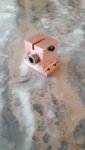
See attached drawing and a pic of the completed prototype.
For any of you that have suffered thru this long winded read.......you will see this mount used on an upcoming " Minamto " build :cryyy:....SO....there are HH applications also!! :san::san:
CDBEAM
I posted this in the " Laser Show " area....for this mount may have application
in a DIY RGB projector build....as well as some advanced HH designs. Warning: Long Read !
For quite some time I have been thinking about a new design for a single 9mm Laser Diode Mount. I see limitations in the current LD Mount design's offered ....and with that, I have generated a new concept called......the " Ultra Mount " .
As typical, I like to incorporate components which are all ready exist" on the shelf"....and....adapt them to my design. "On the shelf" components take advantage of mass quantity supply and inventory currently maintained by other existing reputable suppliers. The Ultra Mount is therefore bundled with the DTR 20mm CU LD Holder.
One problem with the current mounts offered is how difficult it can be to achieve proper LD axis radial orientation. With the standard LD mount, the bolt's on back clamp plate must be loose... so the LD can be rotated into the proper position. Well....then...to rotate the LD, we manipulate the LD by twisting the Anode-Cathode leads. In my opinion... this put stress on these leads due multiple repositioning, and....because the leads flex... precise rotation positioning is very challenging.
Also....when the Standard Mount bolt's ...on back clamp plate are loosened even a very slight amount to allow for LD rotation...the LD focus is changed...and the Far Field goes to a blur. So...how can precise radial orientation be determined...when we are looking at a blur at the Far Field ? It can be done ...but it is tedious and difficult. ....as in..Loosen the back clamp plates.....Rotate the LD.....Tighten down back clamp plate.....observe the " Long Bar " ( the Far Field geometry should be parallel to the Optical work station plane ).
This then is the iterative method I use to set the proper radial alignment when using the Standard Mount. This method requires many, many adjustments to zero in on the correct orientation, and....every adjustment puts additional twisting stress on the LD leads ! It is a time consuming and challenging method....and I think there is a better way.
Another method of LD mounting is the use of the 12 x 60 module...typically the units used with the Hand Held class. With this mount/module ...the LD is press fit into the module. The module unit does provide for smoother radial positioning procedure, as the module, not the LD itself, is rotated to achieve correct radial orientation...BUT...
I am NOT inclined to use a Press Fit between the LD and the mount body. Often, a very small off axis pressing operations....will result in an off axis LD....which then delivers an off axis beam propagation....so... beam alignment will NOT be parallel with the round mount outer perimeter case. In some applications....this is not an issue....and....in some applications...this off-axis condition....IS a problem.
It is true that a Press Fit will deliver a very secure and complete LD base to mount unit contact. This close contact is preferred for good thermal transfer. In my opinion..to compensate when using a clamp fit....just apply a drop of Arctic Silver....and....the degree of Thermal transfer should likely be very, very close to that of a Press Fit.
For a set of Cylindrical lenses to operate properly, we need to have the LD beam slow axis enter the Cylindrical PCV first lens in the correct radial orientation. The LD radial orientation must be correct or Far Field aberration will present.
Mmmm...how to solve these issues ???
I first choose to incorporate the existing LD mount from DTR....the 20mm LD mount. For my preferences....a slight modification of the DTR 20mm LD mount is called for. One only need open the LD bore socket on the DTR unit...just about 0.05mm in diameter.... and the design becomes a friction fit....and NOT a Press Fit.
The thought is...it is smart to use this DTR off-the-shelf component. The 20 mm DTR is very nicely engineered ....and quite reasonable in price !!!
To achieve additional LD base to mount unit contact, the DTR module is of excellent design. To lock in the LD to the DTR mount, the unit front half is screwed into the unit back half ...which brings an internal post up into contact with the back face of the LD. Such clamping pressure surly acts to pull heat from the LD back face !....likely more than enough to compensate for loss of any thermal transfer when we abandon the Press Fit approach.
Now...you may ask....what are the options, when using the DTR Round geometry mount, to fix this mount to any FLAT Optical table or platform. Well....I propose to combine the DTR 20mm mount component....with an external and Rectangular Copper Clamp unit/base....into which the DTR unit is inserted....and clamped.
I must note that this entire "Ultra Mount" design was inspired, over 5 years ago, by a dual clamping mount realized by Logsquared. His design has been "rattling around " in my head for all this time.....and finally, I have used this inspiration to generate the "Ultra Mount"
Such clamp unit/bases have been seen before...nothing new here...EXCEPT...being machined from solid CU !!!...Solid CU is superior to Aluminum or Brass in " Wicking " away heat from the LD. Therefore, I choose solid CU for the Copper Clamp Unit Base...( CUCUB). The use of CU in this area should deliver optimum thermal transfer.
The CUCUB has a 20mm ID thru bore machined. This 20mm ID bore accepts the DTR 20mm mount. The top section, above the 20mm thru bore, will have a 4mm slot machined thru the unit. A 6mm bore thru will be machined, perpendicular to the 4mm slot on the right upright. A 6-35 Allen Head bolt will be screwed into a threaded socket in the left upright. Tightening the 6-35 bolt will then produce clamping action....as the left and right upright are drawn together....and the tightening action then apply lateral clamping force to the DTR unit circumference.
The CUCUB will have two (2) tabs/feet, machined into the unit sides. These tabs or feet will have two (2) bore thru mounting hole in each tab. To fix the CUCUB.....four (4) mounting bolts will secure the unit to the optical platform.
Now....we can have the best of all options. A small 2mm bore x 8mm deep is added to the DTR unit rear outer perimeter. This bore becomes a socket into which any long (10cm) sharp/pointed alignment tool can be inserted into. The LD is aligned while the CUCUB is opened/unclamped.
The DTR module is radially positioned, by use of the alignment tool, to achieve perfect position of the beam axis orientation for presentation to the Cylindrical lens correction optics. Once optimal position is achieved, the CUCUB clamp bolt is tightened...and...we have it all;
1) No multiple twisting of the LD leads, therefore, No extra stress on the LD leads.
2) Easy of precise radial position of the DTR LD Mount...and LD... via the alignment tool.
3) Good thermal transfer from the DTR unit to the CUCUB base due clamping action of the CUCUB uprights.
4) Good thermal transfer and heat absorption by the DTR unit due the addition of mount to LD back contact.
5) Good CU mass for both the DTR unit and the CUCUB Base.
6) Beam propagation Pitch and Yaw adjustments are available by slight shim usage under the CUCUB unit.
7) Secure fixing of the Ultra Mount to the Optical work plane.
In closing, this design is much larger than both the Standard LD mount and the 12 x 60 module. So...if a miniature footprint is your requirement....this is NOT the mount for you. For an advanced design concept, which solves many previous LD mount limitation...this MAY be the mount for you especially for any Projector or advanced Hand Held unit.
See attached drawing and a pic of the completed prototype.
For any of you that have suffered thru this long winded read.......you will see this mount used on an upcoming " Minamto " build :cryyy:....SO....there are HH applications also!! :san::san:
CDBEAM
Attachments

Last edited:


")
")