- Joined
- Jul 4, 2012
- Messages
- 2,832
- Points
- 63
Ask Things, he has a laser cutter (I think its him at least)


Follow along with the video below to see how to install our site as a web app on your home screen.
Note: This feature may not be available in some browsers.


Check out maker labs there is a bit of setup cost, but once that's over you can pop in any time to use the laser cutter.
Awesome! Always thrilled to hear any updates on this. I'm honored to be involved in such an auspicious build.
Remember, I'll help with any kinks in the programming or electronics should the need arise, just ask. =)
") Just stumbled on this thread after seeing your other one for single mode diodes! Excellent work btw, the alignment is sod if you dont have room for mounts! +1 because Im jealous
Just stumbled on this thread after seeing your other one for single mode diodes! Excellent work btw, the alignment is sod if you dont have room for mounts! +1 because Im jealous ") :beer:
:beer:
That's some incredibly detailed CNC work there.
This looks absolutely amazing and I can't wait 'till you finish it :beer:
+1 (btw, I meant to say 'sir' in the rep comment lol)
What kind of code for the attiny13a micro-controller have you based the firmware on? Or did you start from scratch?
When you implement the attiny13a into the final build will it individually address the PWM value for each diode or do you
have something else in mind? Also the voltage limit for the attiny13a is 5.5v so what sort of input voltage are you
working with for the green and blue diodes?
Maybe I've asked too many questions.

No, it's just going to be an on/off situation per channel (so, I'll get yellow, cyan, magenta, but nothing in between). In the driver thread, they didn't think it was possible to control PWM on three channels with an ATTiny.
It was a scratch-built program. I still have no idea how to actually load it onto the chip. I have the chip, and the USB controller, but it's not as easy as the chip showing up as a USB drive and copying the program text
They have a CNC?
So like, I could go CNC my own stuff?


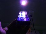
Wow! What is the light we see on the top? Just leakage from the inside, or is that strip illuminated independently?