Welcome to Laser Pointer Forums - discuss green laser pointers, blue laser pointers, and all types of lasers

LPF Donation via Stripe | LPF Donation - Other Methods

Links below open in new window

ArcticMyst Security by Avery

The Green Gargoyle 10.08 W @ 520nm

Joined
Jan 29, 2014
Messages
12,031
Points
113
Well, if you can control them all with one pot, the current through the sense for power control on the BB driver must be extremely small and only skews the adjustment one way or another, so the pot is at a different position for the same amount of power out per diode, no big deal.

Edit: I found this information:

What is the max rpm?
Answer:
The max rpm is: 2200
@ 2200rpm the fan delivers ~ 32 CFM and has 17.7 dB(A)
As this fan uses PWM function the min rpm is 450rpm.
There is a speed adapter in the scope of delivery in case you like to drop the max rpm. In this case the max rpm would be 1750rpm.

Only thing I have not found is the current needed for 2000 RPM.
 
Last edited:


Joined
Feb 25, 2010
Messages
1,643
Points
113
Yea....Paul...Probably China Smoke and mirror on the 5000 mAh…..Will do some research on what is reality...I have info on this...somewhere... on my laptop......BUT....For now....I am assuming this is how we will power the unit....and...of course.....use a good name brand 18650 cell !!

Chris...As to the single pot....well....I feel very comfortable going with what Wossee sez. I got him roped into this project now....lucky him !!

I am still giving thought to our test set up.....1,3 or all 6 LD's ???? Hmmmm...six (6) LD....mounted on the Hex bar. Most realistic test = Six (6) LD's with Heat sink in place and Dual/Stacked fan arrangement....also most involved and costly !

CDBeam
 
Joined
Jan 29, 2014
Messages
12,031
Points
113
I'd just build it and see what happens. I think you have done enough already to be able to move forward with the project.
 
Joined
Feb 25, 2010
Messages
1,643
Points
113
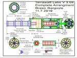
I agree !!!! See my last render.....maybe till next year !!! ( If yer Lucky !!) Will proceede with trials. WEEEEeeeeee !!
 

Attachments

  • avatar9799_7.jpg
    avatar9799_7.jpg
    7.8 KB · Views: 14
  • Green Gargoyle V3.04.JPG
    Green Gargoyle V3.04.JPG
    230.7 KB · Views: 12
Joined
Jul 10, 2015
Messages
9,907
Points
113
I'd just build it and see what happens. I think you have done enough already to be able to move forward with the project.


I think you have a winner, sounds good to build one as slated and test it in the field, maybe version II will see some modifications in the cooling and maybe not but you could make version II with c-lens correction for each beam and/or do one with Red Green Blue Red Green Blue, that would look cool as the big beam would show some RGB leaving the unit then turn white as it heads into the sky, or any color as you adjust the balance of color.
 

Attachments

  • beamprofile.jpg
    beamprofile.jpg
    44.1 KB · Views: 9
Joined
Jan 29, 2014
Messages
12,031
Points
113
Robert, I've been visualizing the same thing in the past about separate R,G,B and he beam turning white as they mix due to divergence.

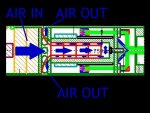
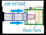
Bob, can you show me how the air circulates back out of the assembly? I still do not have a full understanding of how it circulates.
 
Joined
Jul 10, 2015
Messages
9,907
Points
113
The core is an extruded finned cylinder with a hollow center and that horn separates the inflow and outflow.
Bob I'm sure will also acknowledge your question but that's how I have been seeing it.

Air intake is now around the handle/batt tube from the backside IINM and not around the circumference.

airflow.jpg

airflow2.jpg
 
Last edited:
Joined
Jan 29, 2014
Messages
12,031
Points
113
OK, good, that was how I thought it must work too, but wasn't sure. Thanks Robert.
 
Joined
Feb 25, 2010
Messages
1,643
Points
113
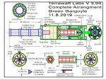
Thanks Robert...Perfect illustration !!! Sucks in da back....and blows out just behind the End of the Hex Bar. See latest render...just some minor refinements......I have been thinking about alignment....and will continue to ponder this challenge !!!

I have many, many ideas how to machine and align....way to many to bore you with !!

These details will provide ease of construction, ease of initial alignment, stability of the alignment and the ability to re-align. All important details....for sure....but not for this format.

I am now in discussion with the Alaskan on how to proceede with some basic testing. I remain very hopeful that the dual stacked fan arrangement will be sufficient for heat removal.

For now.....I will stop my manic posting and CAD drawing excise !! This preparation work is tedious.....but must be done to forge a tentative plan.
I think we can agree, this entire project is ambitious and ground breaking......Hot Diggity !!

I will report back when some test metrics are available on the thermal results.

CDBEAM
 

Attachments

  • Green Gargoyle V3.04.JPG
    Green Gargoyle V3.04.JPG
    236.7 KB · Views: 9
Joined
Jan 29, 2014
Messages
12,031
Points
113
Great, looking good. I ordered two of those fans the other day as well as a couple of different PWM motor driver boards to try too.
 
Joined
Feb 25, 2010
Messages
1,643
Points
113
Yes...I believe this is the premium 80mm fan to use. I think Noctura is the top of the line ! I also cannot locate the amp draw !
I have also found a small form factor 10A PWM unit. I have never tried to control a 4 Pin Computer Fan with a discrete PWM controller. As usual....I suspect there is more involved than my rudimentary understanding covers. The Devil is always in the Details !!

CDBeam
 
Last edited:
Joined
Jul 10, 2015
Messages
9,907
Points
113
The 4 wire brushless PC fans usually take 12v and will run just with 12v but the other 2 wires are a tachometer output and the PWM speed control which you use witn the common ground, so you can control the fan speed with a PWM signal but it's not carrying any real current to drive the fan, rather it's just a control signal.

 
Joined
Jan 29, 2014
Messages
12,031
Points
113
Bob,

Have some of the parts ready to send, I don't have the lasertack mirror mounts we need, unless you want to use the type with two threaded screw holes which mount to their knife edge plate assembly. I put the diode mounts together with G8 lenses.

1. 3 each NDG7475T
2. 8 each BB 8
3. 8 each Lasertack green mirrors
4. 8 each G8 lenses
5. 10 each Lasertack 9 mm laser diode mounts.


What do you think of this for an airflow funnel? We could cut it down to fit :)


Last edited:
Joined
Feb 25, 2010
Messages
1,643
Points
113
Well.... JUST PERFECT for the Air Flow Funnel !!!!!!!!!!!!!!!! And...It is available in different size funnels.. 21mm ~ 36mm....Wow......NOW...that makes sense !!!...and....it is not susceptible to moisture...no surprise there !! We are just so DAMN clever...See....I always am a proponent of " Off the Shelf " components...and...this surly qualifies !!! Chris...you are a Real Genius !!!......Whada think LPF ??? I say...Chris....." You graduate....you get the job " !!!!!! Time to mix it up around here !!!!! It is a Moral Imperative.....to do so !!!

CDBeam
 

Attachments

  • V__Calander_9_Simon_The_Hunter_by_The_Man_Of_Tomorrow.jpg
    V__Calander_9_Simon_The_Hunter_by_The_Man_Of_Tomorrow.jpg
    9.4 KB · Views: 2
  • robert_crumb not here to be polite.jpg
    robert_crumb not here to be polite.jpg
    226.7 KB · Views: 1
Last edited:
Joined
Jan 29, 2014
Messages
12,031
Points
113
I have a lot of help :) BTW, the mirror mounts have been ordered drop ship to your home address. Enough mounts for three of these beasts plus two spare.

(edit: I will increase the number of 9 mm laser diode mounts to build three too, I already have them, will send with the other stuff).

Chris
 
Last edited:


Top