Welcome to Laser Pointer Forums - discuss green laser pointers, blue laser pointers, and all types of lasers

Buy Site Supporter Role (remove some ads) | LPF Donations

Links below open in new window

FrozenGate by Avery

Tesla Coil Build Thread

Ya, internal diodes are always too slow/small for TC purposes and should be bypassed with MUR series ultrafast high-current diodes. You'll notice a major drop in heating.

Thanks!

I just realized today I can remove the 555 chip to see how it functions in CW, haha. So I did that and it still runs great with not much more heating, but again this primary is high impedance and only lets a small current through. Nice to know it works fine though. I DO hear 120Hz overlay though so I need better filtering on my mains DC buss. That is the next step now, then put in a switch to turn off the 555 for easy CW operation.

Is anyone familiar with 555 PWM topology? I've never really used it and could use a refresher (or a link to a refresher). I know 555 astable/bistable very well though, but its PWM output, scheme, method of operation, and range, is all new to me. And without a scope I can't just take a look while turning potientiometer knobs, hehe.

BTW, Ionlaser555, How did you apply the audio modulation to the cathode Mosfet in your coil? I was thinking of using a Schmitt Trigger to feed the enable pins of my UCC Gate Drive chips with a square wave form of input audio, but I think that would probably distort the audio heavily. I know that works for Midi modulation very well, but I don't think it would work for true analogue audio. You got awesome fidelity on yours so I'm curious how you did it.
 
Last edited:


Ya, internal diodes are always too slow/small for TC purposes and should be bypassed with MUR series ultrafast high-current diodes. You'll notice a major drop in heating.

Thanks!

I just realized today I can remove the 555 chip to see how it functions in CW, haha. So I did that and it still runs great with not much more heating, but again this primary is high impedance and only lets a small current through. Nice to know it works fine though. I DO hear 120Hz overlay though so I need better filtering on my mains DC buss. That is the next step now, then put in a switch to turn off the 555 for easy CW operation.

Is anyone familiar with 555 PWM topology? I've never really used it and could use a refresher (or a link to a refresher). I know 555 astable/bistable very well though, but its PWM output, scheme, method of operation, and range, is all new to me. And without a scope I can't just take a look while turning potientiometer knobs, hehe.

BTW, Ionlaser555, How did you apply the audio modulation to the cathode Mosfet in your coil? I was thinking of using a Schmitt Trigger to feed the enable pins of my UCC Gate Drive chips with a square wave form of input audio, but I think that would probably distort the audio heavily. I know that works for Midi modulation very well, but I don't think it would work for true analogue audio. You got awesome fidelity on yours so I'm curious how you did it.

Hey, I just saw your recent videos with the new SSTC. I got to say, it is nicely built!!
500Khz? look like quite high frequency. It really puts out a nice EM field !!
I too got 120Hz from your audio in the video. You got sinewave output from MOSFETs?

Great work!! +1 again!! keep those cool videos coming. Really like your progression!
 
Last edited:
.

BTW, Ionlaser555, How did you apply the audio modulation to the cathode Mosfet in your coil? I was thinking of using a Schmitt Trigger to feed the enable pins of my UCC Gate Drive chips with a square wave form of input audio, but I think that would probably distort the audio heavily. I know that works for Midi modulation very well, but I don't think it would work for true analogue audio. You got awesome fidelity on yours so I'm curious how you did it.

Thanks :)

Cathode Modulation was on my VTTC it was a mosfet biased to conduct then the audio signal varied the conduction level i think , For My SSTC im using a PLL with a VCO , the VCO is biased though a 10nF Cap and 100 Ohm resistor to ground then a audio signal is applied across the resistor , and as the capacitor is connected to the VCO inputpin the varying voltage from the audio varies the VCO oscilation frequency , producing the sound .
 
Last edited:
Hey, I just saw your recent videos with the new SSTC. I got to say, it is nicely built!!
500Khz? look like quite high frequency. It really puts out a nice EM field !!
I too got 120Hz from your audio in the video. You got sinewave output from MOSFETs?

Great work!! +1 again!! keep those cool videos coming. Really like your progression!

Thanks! I calculated the self-resonant frequency of the secondary to 1.175MHz actually. If I can find a 2" sphere (doorknob) the fres should drop to around 1MHz. Now, this wire tends to have a higher capacitance than JavaTC calculates, which means the fres estimates are high. Based on what I learned from my SGTC tuning endeavors I would say they are around 10% too high. So, I consider this to be a 1MHz SSTC.

The 120Hz modulation you hear is actually the ripple in the supply voltage of the HV DC Buss left over from fullwave rectification of the mains power. When I disconnect the mains but leave the driver on, the 120hz oscillation disappears for the second or so it takes for the filter caps to fully discharge (at which point there is still some output, though rapidly diminishing).

If I get a chance before work I'll throw the other two 460uF 200V caps on the mains bridge and see if I can't eliminate the 120Hz modulation.

Thanks :)

Cathode Modulation was on my VTTC it was a mosfet biased to conduct then the audio signal varied the conduction level i think , For My SSTC im using a PLL with a VCO , the VCO is biased though a 10nF Cap and 100 Ohm resistor to ground then a audio signal is applied across the resistor , and as the capacitor is connected to the VCO inputpin the varying voltage from the audio varies the VCO oscilation frequency , producing the sound .

Ahhhh okay my initial suspicion was that you were using a mosfet as a power amplifier, but then I started thinking about how much power would be dissipated in a fet operated in the linear region at the voltage and current levels your VTTC ran at and shrugged it off as impossible. Kudos to you for making it work!

I am actually looking at doing similar for my SSTC. Having voltage ripple from insufficient mains bridge filtration cause 120Hz audio modulation of the output gave me the idea to run a linear biased mosfet as an audio amp for audio modulation of my SSTC. I figured I would see if that was what you were doing as well, to determine the viability. Now I am just wondering if it would be better to place the amplifier mosfet between the half bridge and ground or on the high side. I am thinking that it would be simpler between bridge and ground as this means I would not have to isolate the gate drive for the fet with a transformer, as Source would be at ground potential. I'd still use an audio isolation transformer to protect the audio source though.

Very nice with the SSTC, using a PLL with VCO, that is brilliant! I've never worked with PPLs and am unfamiliar with the chipsets. Your board looked far more simple to lay out (with about 1/3 or less of the parts too!) than mine. Can you post a schematic of your driver and link to datasheet for that PLL chip (or just it's full part number/name) please?
 
Absolutely beautiful!


Btw, I increased the coupling of my SSTC and doubled if not trippled the power. Unfortunately that crappy primary died and I will make the brand new one with good wire tomorrow on my day off. I also decomissioned my SGTC. I'm saving the secondary but I think the rest will be resold/reused for other things. I'd like to sell the MMC and NST as a matched pair (since they are!).
 
Thanks! I calculated the self-resonant frequency of the secondary to 1.175MHz actually. If I can find a 2" sphere (doorknob) the fres should drop to around 1MHz. Now, this wire tends to have a higher capacitance than JavaTC calculates, which means the fres estimates are high. Based on what I learned from my SGTC tuning endeavors I would say they are around 10% too high. So, I consider this to be a 1MHz SSTC.

The 120Hz modulation you hear is actually the ripple in the supply voltage of the HV DC Buss left over from fullwave rectification of the mains power. When I disconnect the mains but leave the driver on, the 120hz oscillation disappears for the second or so it takes for the filter caps to fully discharge (at which point there is still some output, though rapidly diminishing).

If I get a chance before work I'll throw the other two 460uF 200V caps on the mains bridge and see if I can't eliminate the 120Hz modulation.


Ahhhh okay my initial suspicion was that you were using a mosfet as a power amplifier, but then I started thinking about how much power would be dissipated in a fet operated in the linear region at the voltage and current levels your VTTC ran at and shrugged it off as impossible. Kudos to you for making it work!

I am actually looking at doing similar for my SSTC. Having voltage ripple from insufficient mains bridge filtration cause 120Hz audio modulation of the output gave me the idea to run a linear biased mosfet as an audio amp for audio modulation of my SSTC. I figured I would see if that was what you were doing as well, to determine the viability. Now I am just wondering if it would be better to place the amplifier mosfet between the half bridge and ground or on the high side. I am thinking that it would be simpler between bridge and ground as this means I would not have to isolate the gate drive for the fet with a transformer, as Source would be at ground potential. I'd still use an audio isolation transformer to protect the audio source though.

Very nice with the SSTC, using a PLL with VCO, that is brilliant! I've never worked with PPLs and am unfamiliar with the chipsets. Your board looked far more simple to lay out (with about 1/3 or less of the parts too!) than mine. Can you post a schematic of your driver and link to datasheet for that PLL chip (or just it's full part number/name) please?

Wow, no wonder the sparks are so stubby. At 1Mhz Your sparks are going to short and fat.
I bet you you could make a decent plasma tweeter out of the coil!!
Again, well done!! Nice intro into SSTC's!!!
One of these days when I get around to it, I may build a large SSTC. It's $$$$ I don't have at the moment. I may move to another city in SK or go back in August to Canada.
Exhausted from the 5 or 6 or so interviews I have done in the past 3.5-4 months.
 
Today I experimented with the interrupter a bit and found it to be very limited and IMO useless for such a high fres coil. So, I clipped the leads and converted my driver to CW only. I also rebuilt the primary with the new wire and coilform and put my topload sphere on it.

Results: SSTC V2.0 - Final Iteration - YouTube


Specs are in the video description.

My plans now are to build another driver circuit utilizing the spare parts I have (I ordered double of everything the first time) but without the interrupter sub-circuit. I'll put in a jumper style connection for the addition of a much better interrupter later on as well. I'm not going to modify this driver any further, I want to always have a working coil on hand at all times from here on out. The second driver I'll probably hook up to my large secondary.

I did the math and in order to achieve a 1Vp-p ripple on the DC buss I would need ~40,000uF of filter capacitance rated for >200V. That is some serious cash there as the best capacitance/dollar is $2.85 for 470uF which would take 86 capacitors.... nearly $300! So, I will not be going for audio modulation any time soon.

I am thinking of making a VTTC in the future and audio modulating that though!

In the video I may have mis-spoken a few times about the numbers, it is over 97F in here with no airconditioning.
 
Nice Work on the SSTC :) 1Mhz Wow Mines only 190 - 200Khz , Thanks :D Info on the PLL Circuit i used can be found here SOLID STATE as i just used his desing but replaced antener feedback with CT Feedback insted .

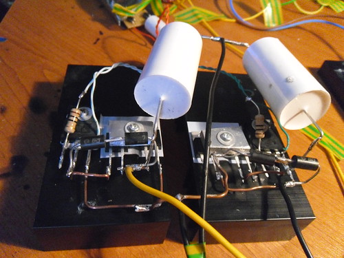
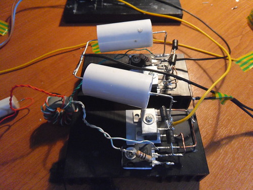
Today i updated the Half bridge i have isolated the Mosfets body diodes , but i still get heating ; after 10 seconds run time heatsink is warm , Its either the schottky diode or the ultra fast diode producing the most heat as the area under mosfet is the least warm , its warmest under the 2 diodes after the run . maybe to lower current rating of the schottky diode ( 4A ) is causing the heating ?

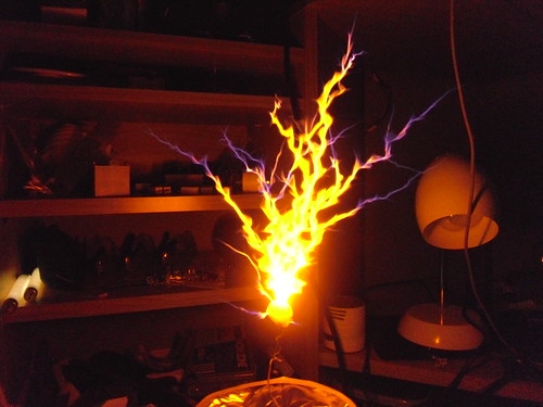
To target/free air with Fullwave supply and no smoothing i get 8 inch arcs . larger topload i hit 9 inches .

SSTC Half bridge Test - YouTube Quick run of the SSTC

http://www.youtube.com/watch?v=REBw_z50Pvc&feature=youtu.be Smoothed DC CW Run :P


SAM_0614 by TwirlyWhirly555, on Flickr


SAM_0612 by TwirlyWhirly555, on Flickr


SAM_0599 by TwirlyWhirly555, on Flickr
 
Last edited:
Wish I could get big heatsinks like the ones you use. Across the pond they don't seem to have a retailer. The ones I am using are for TO-263 chips and sold by Mouser for nearly $4 a piece.

Ahh, that explains why your arcs are so much larger than mine! Yeah, there seems to be an almost linear inversely proportional relation between arc length and frequency. How big is your secondary? Mine is 8" of 30ga on a 3.25" pvc form. I have my BIG secondary from my SGTC which has a fres near 160KHz which I may try in the future.


UPDATE: Finishing disassembling my SGTC and put my SSTC in it's place across the room.... all the 120Hz modulation noise disappeared!

http://youtu.be/yIDI57paVlQ
 
Last edited:
Hi ,

Nice , My secondary is 4" x 6" 28 or 30 AWG wire on it

edit : with a larger topload and 8 Turns i hit 9 inch arcs , then both mosfets diode . now using 2 ultrafast diode on each Fet one as mosfet body diode isolator and second one was freewheeling diode and 10 primary turns i get 8 - 9 inch arcs little heating and no dead silicon ( touch wood ) :D
 
Last edited:
Today I experimented with the interrupter a bit and found it to be very limited and IMO useless for such a high fres coil. So, I clipped the leads and converted my driver to CW only. I also rebuilt the primary with the new wire and coilform and put my topload sphere on it.

Results: SSTC V2.0 - Final Iteration - YouTube


Specs are in the video description.

My plans now are to build another driver circuit utilizing the spare parts I have (I ordered double of everything the first time) but without the interrupter sub-circuit. I'll put in a jumper style connection for the addition of a much better interrupter later on as well. I'm not going to modify this driver any further, I want to always have a working coil on hand at all times from here on out. The second driver I'll probably hook up to my large secondary.

I did the math and in order to achieve a 1Vp-p ripple on the DC buss I would need ~40,000uF of filter capacitance rated for >200V. That is some serious cash there as the best capacitance/dollar is $2.85 for 470uF which would take 86 capacitors.... nearly $300! So, I will not be going for audio modulation any time soon.

I am thinking of making a VTTC in the future and audio modulating that though!

In the video I may have mis-spoken a few times about the numbers, it is over 97F in here with no airconditioning.

Hey, stella has her spark back!!! Nice work!!! +1 for you!! Now that's a much bigger spark. I think your frequency also adjusted down lower? The added top load sure has made a noticable difference.
 
So I've been working my ass off at my new job lately, which is why it has taken so long to reply with an update. I only get one day where I can use several hours for free time, the other I am managing my responsibilities. This job is such that I am away 11hrs a day (work + commute) and I do nothing other than eat, sleep, work, and bio-functions.

Anyway.... here's my pride and joy:

A nearly 1KW SSTC! Large Solid State Tesla Coil - ~1kW of Power! - YouTube
 
This will probably sound stupid but is there a reason I can't use the same simple 555 flyback driver to drive a really small SSTC? Wouldn't it just be a matter or adjusting the frequency?


Back
Top