Welcome to Laser Pointer Forums - discuss green laser pointers, blue laser pointers, and all types of lasers

Buy Site Supporter Role (remove some ads) | LPF Donations

Links below open in new window

FrozenGate by Avery

TEC Basics - Do they need to be driven?

Hmmmm... Can we use a TEC to more accuratly move the heat from the diode to external fins? I am again... just looking at how my cpu cooler worked :-P It had "pipelines" that lifted off the cpu into a huge "fin block" that was cooled by a fan.

P.S. (i know it doesnt get rid of the heat :-P.. why I asked how we can cool the hot side of the plate)

Has anyone ever made a water cooled block haha? Running a line from the heat sink to the outside of the unit and back would lose quite a bit of heat :-P... who knows how small of a pump we could find tho lol

HAHAHAHA (http://www.xavitech.com/?gclid=CNiqtc-fwqcCFcW5KgodQ1RTJg) TINY water pump

P.S.S What if we had a simply circut that would turn the TEC on for 30 seconds, off 30 seconds, on 30 seconds.... blah blah blah?
 
Last edited:


yes you can. but with tec's you need to watch out for condesation. also note that you really dont need a tec for a laser un less you plan to over drive it. if max power and experimentation is your goal try combining two lowered power lasers via PBS and make one beam.

michael.
 
I know I will get shunned.... I am looking to build a 1W 445 atm... It will be my first build but I really dont feel like making something that will just sit around after a week..
(I'll want a more powerful one)

I tried searching for PBS (as I am a total newb and want to learn) and it comes up with nada. A little insight? And how hard is it to allign, power, drive etc a 2 diode laser?

Thanks!
 
I have a few TEC's, for yours a 60watt, will need 12v at 5amps, 12 v x 5 = 60watts.

I have a PSU from a PS3 which is 12v @ 32AMPS max.
 
Does anyone know the specs on the TEC that's inside a KasEO projector ?
IE - the voltage to feed it, and how much the temperature differential is?
 
It's difficult to say, without a part number, but we can try to guess .....

About the differential temperature, that is an intrinsic value for almost all the TECs, and usually cannot be higher than 70C, in the maximum efficent conditions, for each plaque (layer) of cells ..... it's a phisical limit of the Peltier cells architecture, so if you need more differential, the only solution is to place 2 or more plates one over the other.

About the voltage, it depend ..... they "APPEAR" to be small-junctions 254-cells units (still doing some experiments for discover this part ), and this gives the impression that they may work at least at 24V, more probably also 36V (this is not so immediate, but, usually, you have a 0.125V for each junction, in "standard" cells ..... means, usual 12V cells are 98-elements cells) ..... this drive me to think that for this cell, depending from the rated current (that we still NOT know), it can be rated for work between 24 and 36V .....

The only way for know this, anyway, is to get someone with a working projector and an oscilloscope, and ask him to check the output on the TEC connector (CN205 on the switching PCB, IIRC) ..... you need a scope, anyway, cause the TEC is feeded directly from the output of a switching driver, and may also be PWM drived .....
 
Measuring that wouldn't give you an answer to the maximum rating either, though it will give you a value that is certain to be safe. I think its likely that they operate quite a bit beyond their maximum capacity in a projector, since that projector would also have to work in a higher ambient temperature etc.

I suppose the only way to find the maximum is a desctructive test.
 
I may just trial and error it with some "safe" values"
 
If you know the ballpark figures, i guess that could be done too. Just sandwich the module between two heatsinks, and observe how the temperature difference reacts to increases in current. At some point it will level off since the module is producing so much heat it can't keep the cool side cool anymore.

Afaik for most TEC modules (like the ones for cpus) they can be driven this hard without any damage - as long as you keep it properly heat and coldsinked.
 
TEC's don't like ripple on their drive and I suggest it be kept below 15%. Also, for PWM, keep frequency abowe 5 kHz.

Usually if a module is rated for 12v max, it should not be operated abowe 9.6v (80%) as abowe this level, it produces more heat than it pumps and it's pumping efficiency goes down fast too. Many 12v elements sold for PC cooling are really 15v max elements.

Normal 80c max TEC's have a solder-flow temp of around 138c internally. High temp units come with 183 or 232c solder and are usually rated for 150c on hot side.

If you run simple ON/OFF cycling it is often recommended to keep each cycle atleast 60 seconds.

You normally don't want to just run a TEC directly at constant power unless thermal source is constant and always on. This can lead to low temps causing condensation whenever the thermal source is in low-power mode or off. The high swing in temperatures is stressing the source too.

Ideally a high frequency switchmode reg with temp-probe on cold-side for regulation, and alarm for hot side in case of cooling failure should be used. Using ambient sensoir too and limiting cooling to less than 10c below ambient you avoid condensation in most situations.
 
TEC's don't like ripple on their drive and I suggest it be kept below 15%. Also, for PWM, keep frequency abowe 5 kHz.

If you run simple ON/OFF cycling it is often recommended to keep each cycle atleast 60 seconds.

Interesting. Why?
 
Interesting. Why?

Basically ripple in the current will cause I^2*R losses that will be higher than that of a smoothly driven element, thus reducing the COP. There is also claims from some manufacturers that the ripple causes degraded life expectancy of the modules.

-- edit --
Some mfg's claim over 1kHz others over 5 kHz. Most integrated drivers run in the 500kHz range. This also reduces the needed size of inductors.

Also, running the TEC in PWM without filtering will cause it to have to run at much higher current when on, than average and thus it will really be operating in a different area of COP.
IMagine running it at 100% power 60% of the time. That should have brought you to it's ideal operating point (or close) but since the current is either on or off it's either way past it's ideal point and into the overload zone, or it's not working at all. TEC's are semiconductor devices and as such they respond quickly. It may take a few secs for the sides to start to change temp, but that is heat moving. The process starts almost instantly when power is applied.

Datasheets for some Supercool/Laird tec's: https://www1.elfa.se/data1/wwwroot/assets/datasheets/jwThermoelectric-Mes_en.pdf
Melcor sheets: https://www1.elfa.se/data1/wwwroot/assets/datasheets/id680024_e.pdf
Custom Thermoelectric: http://www.customthermoelectric.com/tecs_imax.html
-- end edit --

The on-off cyceling is probably a lifetime thing, or to allow the plates to fully settle between each cycle. There is actually specially designed elements for cycle-use. They are only soldered on one side in the element, leaving the other side "floating/sliding" to leviate thermal stress. This is common on the large modules and require them to be under higher clamping pressure for equal transfer.
 
Last edited:
So when you say >5KHz, you mean the switching mechanism, and the TEC itself will see DC?
 
Last edited:
So when you say >5KHz, you mean the switching mechanism, and the TEC itself will see DC?

That is correct. The high frequency together with maby an output cap will present DC to the TEC.

The main reason many pwm controllers for TEC's go to 500 Khz or more is probably to support modulation. You want multiple pwm cycles pr pulse to achieve good regulation and targeted output-currents for each pulse.
 
If you drive your TEC moderately and you find a ok powerlevel to give a dT you can live with, you don't really need a driver though.
I am planning to add a temperature-feedback on my cold-block and use that with a driver but for testing I am running it at 5v only. (5v 0.5 amps)

The element is a 40x40x3.9mm module specced at Pcool max 60w at 6 A.
Vmax is 15.7v which means running of a PSU 12v rail puts it at 76% and in the sweetspot even at continous running.
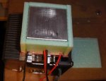
It would however be too much for a small coldblock with a simple 2-400 mW LD in it. Attached is some pictures of how I insulated mine, allowing it to cool to 10-16c with only 2.5w input. There will be a acrylic pressureplate ontop clamping down to the heatsink.

Whenever you cool below ambient you should insulate the cold side to avoid heat recirculating from hot to cold as well as cold-side sucking heat from room. It will allow you to use a smaller/cheaper TEC as well as powersupply and regulator. Let the TEC handle the power it is supposed to, the waste heat from the LD, and nothing more.
 

Attachments

  • cooling_1_s.jpg
    cooling_1_s.jpg
    90.6 KB · Views: 299
  • cooling_2_s.jpg
    cooling_2_s.jpg
    91.5 KB · Views: 288
Nice article with some graphs of LD output vs temps.
Uncooled devices challenge designers - Laser Focus World

Very interesting and they also show the folding from overdrive.
The graphs are for a relatively low power LD though, and if we were to try and create the same graph at 300+ mW powerlevels it would most likely distroy the LD.

I will most definately run mine at atleast 8c below room.
I want the most out of it without condensation.


Back
Top