Welcome to Laser Pointer Forums - discuss green laser pointers, blue laser pointers, and all types of lasers

Buy Site Supporter Role (remove some ads) | LPF Donations

Links below open in new window

FrozenGate by Avery

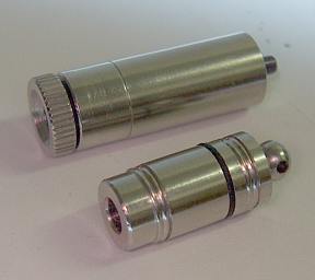
Stand-alone aixiz

the batteries I'm using are basic lr44 or lr45's. Nothing special about them. I do have three of them in series with no additional components so it's straight off the batts. Like I said. it's not a burnin beast but it does do the job. Another thing that annoys me is there is no on/off switch, so I have to keep a paper board in between the batteries when not in use.

I'll eventually get around to making a switch for the tail section of this but it's not a high priority for me right now.


Laserrod said:
I want the specs on your tiny titan ::)

gimee gimee gimee ;D

Very unique

To whom are you referring. This is where quoting comes in very handy.
 
Kenom those 1/2AAA's are lithiums 3.6v that give about 300ma, But i love what you did it looks damn fine.
 
This will be my next challenge:

hpim4181_small.jpg


It barely fits 2 ag3 cells and a 5mm led (its former use)
 
I made a CDrom spectroscope which is more accurate than my previous one, and measured all my reds. This particular red is somewhere in the middle of the extremes. Assuming (no way to verify) that the extremes are 630 and 660nm, this baby is 645mn.
 
I'm making progress on the tiny case in the photo above.

I needed a driver that can drive a laser diode from one button cell. I considered the PR4401 LED driver.

070100-51.jpg


It gives sharp pulses, which are limited and smeared over time by the load. I feared that it would blow the laser, but I went ahead anyway. It seems to work. Then when I tried to measure the voltage over the diode with an oscilloscope, COD suddenly occurred. I was also seeing spikes of up to 10V(!). I figured the 1MOhm load of the probe must have interfered with the inductor, causing strange waveforms to appear. I hooked up another LD and tested some more, and it still works fine.

I took the parts from the PR4401 sample board an soldered them directly to the LD. I had to cut away 2 legs of the LD to make room.

Hpim4222_small.jpg


Closeup:
Hpim4222_closeup.jpg


I attached some springs, glued the LD in the case behind a spacer, and this is the initial result:
Hpim4223_small.jpg


This is a cross-section diagram of my plan:
microlaser.gif


The spacer is there because the case of the LD is Anode, and it's potential is the one generated by the driver, not + or - supply.

The glue is drying at the moment so tomorrow I'll demonstrate the finished product.
 
Finished

Hpim4226_small.jpg


Hpim4229_small.jpg


Intensity comparisons:
Hpim4230_small.jpg

Hpim4231_small.jpg


The spot size still smaller than 4.5 mm after 10 feet. Aperture is 3.0 mm. Beam convergence is 2.4mRad. I think the distortion is because the lens is pressed into the house with great force, and has malformed slightly.


The only downside is that I have to take the battery out to turn it off. I have been experimenting with a magnetic switch using several thin magnets, but only with partial success.
 
toked323 said:
were did you get the driver from? Loooks Nice
I got the completed circuit board from Elektuur/Elektor (old/new name), a Dutch/German/Belgian electronics journal. The driver and inductor are from Prema Semiconductor and Würth Elektronik, respectively. I have no idea how many Henry the inductor is.
 
You are geniuses, building these things that tiny!

I especially like the idea of making at actual 3d rendition of the components in some odd configuration to make it fit.

Somehow i feel very sloppy about my haywire electronics work now - i usually just start and see what i end up with. That does work, but not this small ;)


Back
Top