Pman
0
- Joined
- Nov 28, 2012
- Messages
- 4,441
- Points
- 113
I've built a lot of pens lately and I will share them all coming up but for now I want to show how I built a PLP520B1 (which is a multi-mode but has a small spot size albeit with wings or a line) into an empty CNI pen that I had purchased from Crazyspaz. I haven't a clue what was originally in the CNI pen to begin with but it was meant to run off (2) CR2 cells which you can buy as rechargeables such as a TR 15270 or LiFePO4. I do have some of those cells but decided to go with a single 14500 as I needed the space.
It took me quite awhile to decide what to put in it as I wanted it to be special because the host is special. I CAN make it focus-able if I want to but for now haven't. I'll explain that as I go along.
I forgot to take a pic of the host with nothing in it before starting the build so my apologies. It's not like you wont be able to follow along anyways.
One of the parts it came with was this spacer that had a spring on the end. I added the red wire to it:
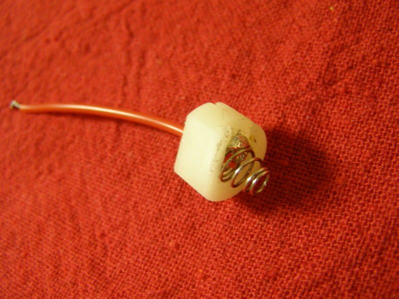
There was already a hole going through it so I just fed the wire. What it doesn't show is I had to trim the whole plastic/nylon piece a bit on the back side where the switch is going to go so that it would line up with the host hole:
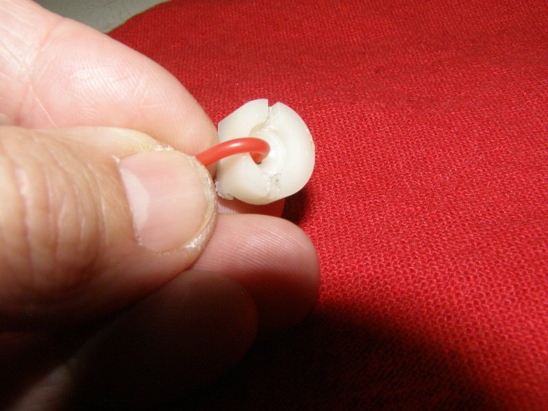
In order to fit the switch correctly I drilled a small hole at an angle for the negative wire:
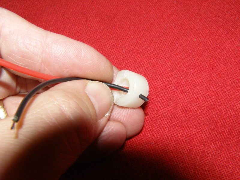
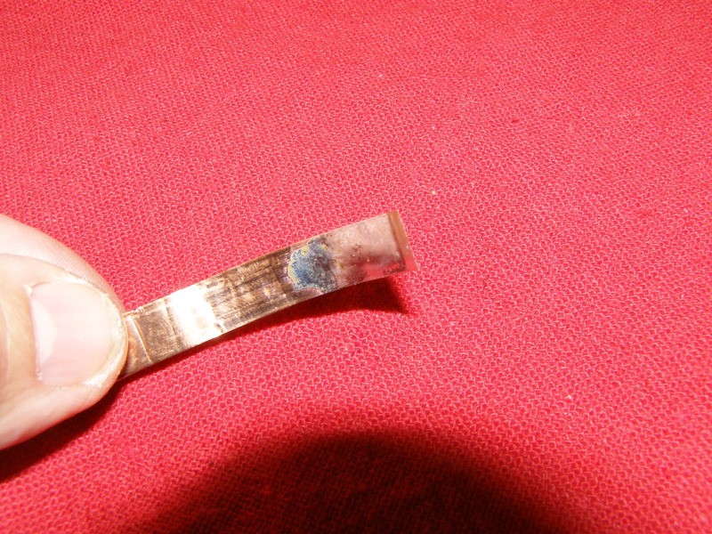
The reason why I fed the negative wire through that piece is to make a way for the drive to catch the negative off the host wall just as I've figured out to do with all my laser66 builds (and there's a bunch finished I haven't shared yet . I took a piece of thin copper and tinned it on both sides for a bit of added thickness and to make good contact with the host. It works VERY well:
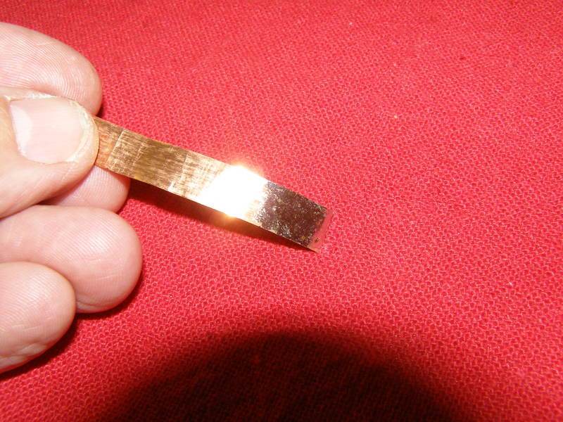
Soldered the negative wire to the copper:
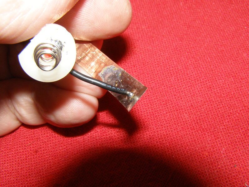
Trimmed down this is what it actually looks like:
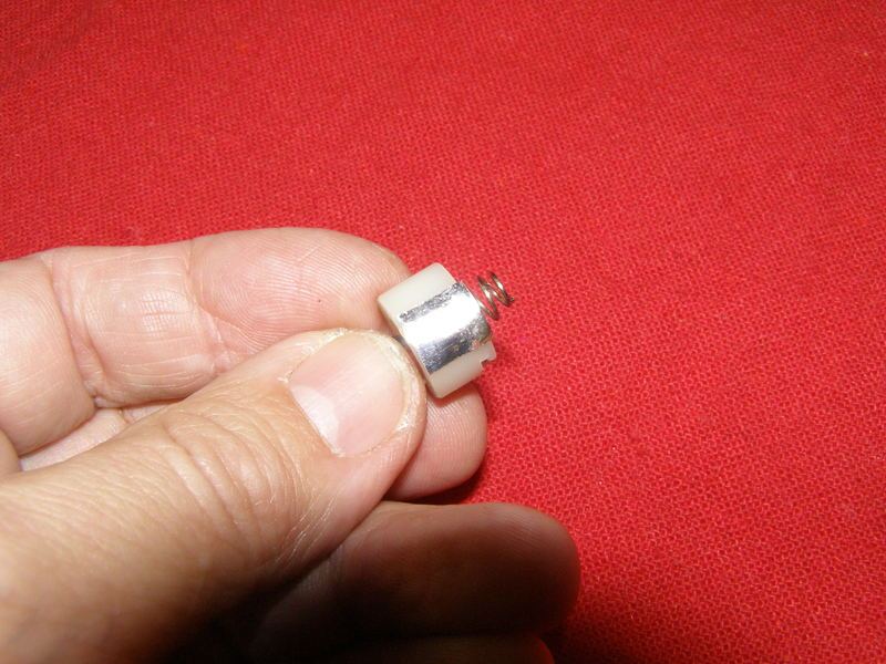
After removing all the components on the switch/driver and checking my options of where to solder the other end of the negative wire to this is what I ended up with:
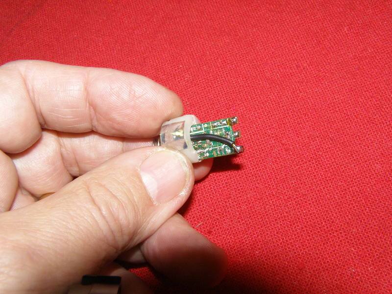
I then soldered the + to the other side of the switch:
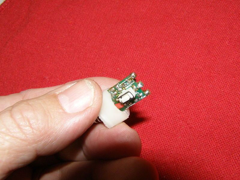
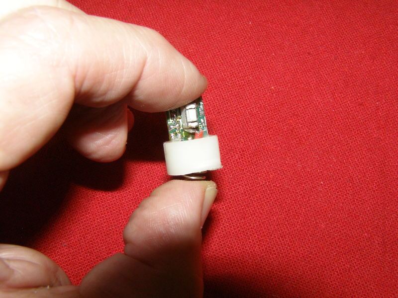
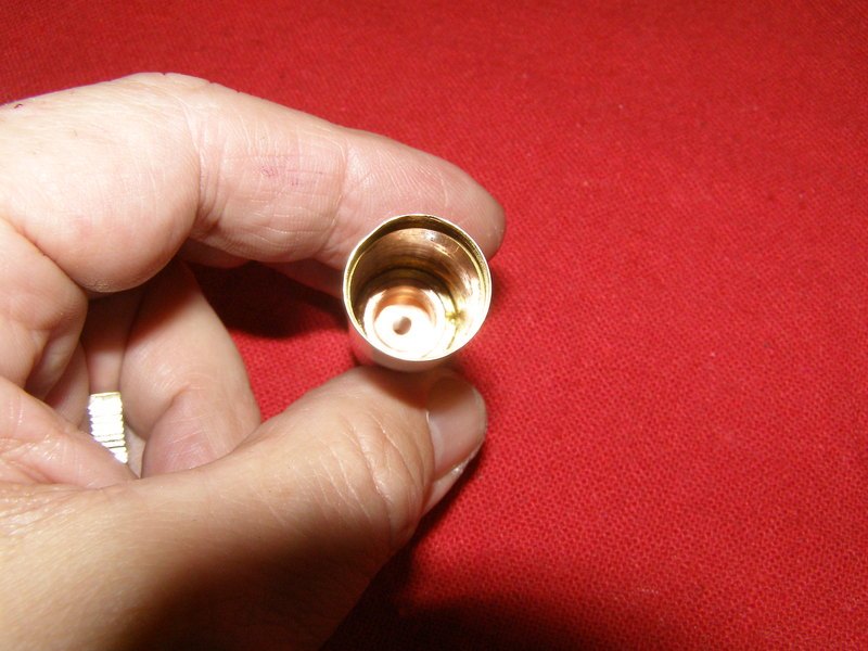
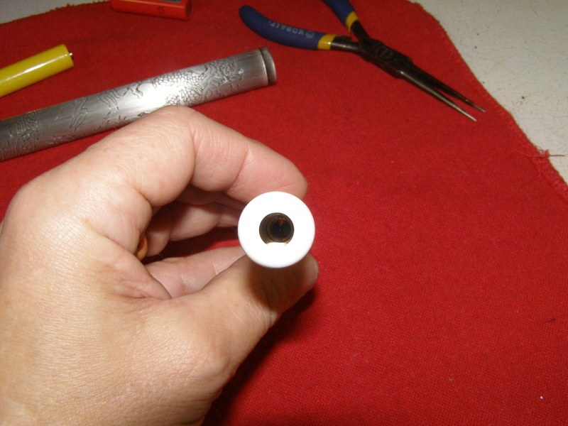
Looking down one end of the top section you can see there is a brass piece in there for a module to be pressed into:
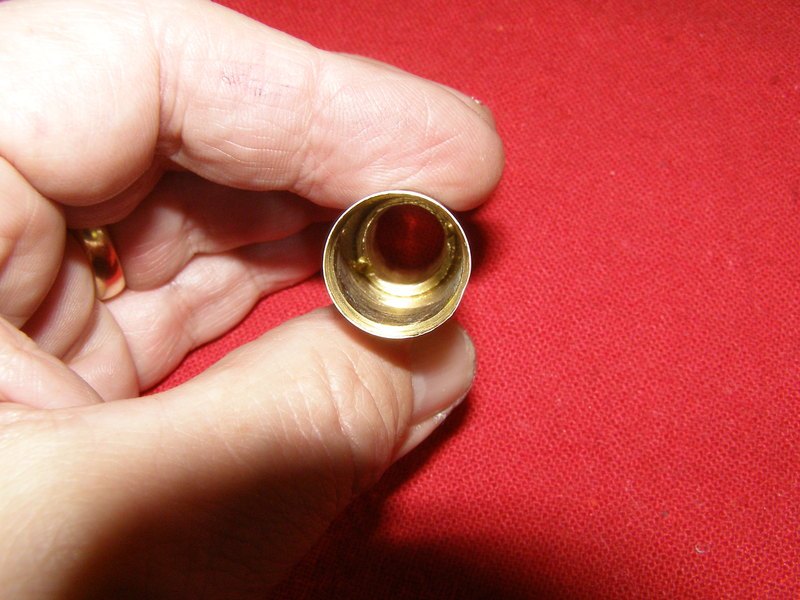
This is the other end and it sticks out so the back half can press into it snuggly. All the scrapes were there when I got it and my guess is that something drastic had to be done to remove the innards:
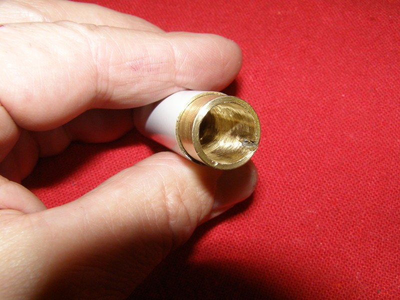
I had to trim the end down a bit so everything would fit properly. Please keep in mind that I only have hand tools lol:
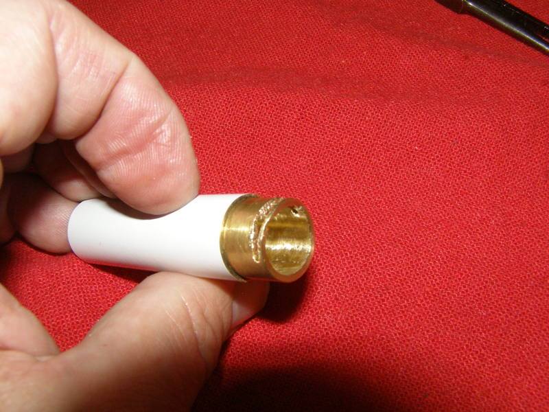
What you see here is the back half with the switch pressed into place:
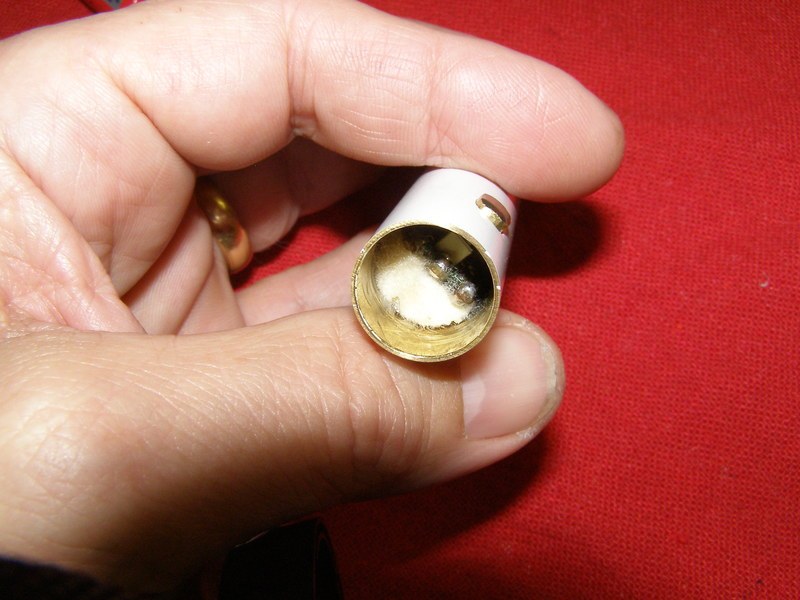
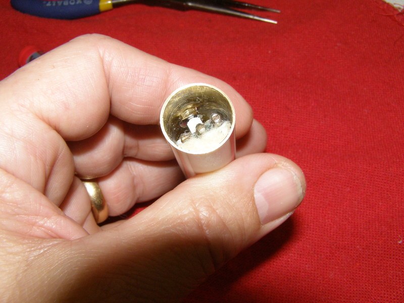
Something of interest is I ended up having to change out the switch (just the actual small switch part on the board) and because of how this piece fit I needed to trim down the rubber boot that was supposed to slip inside over the button but while I was slimming it down with my dremel it flung off to parts unknown to never be seen again so I also modified for a different button to stick through the hole.
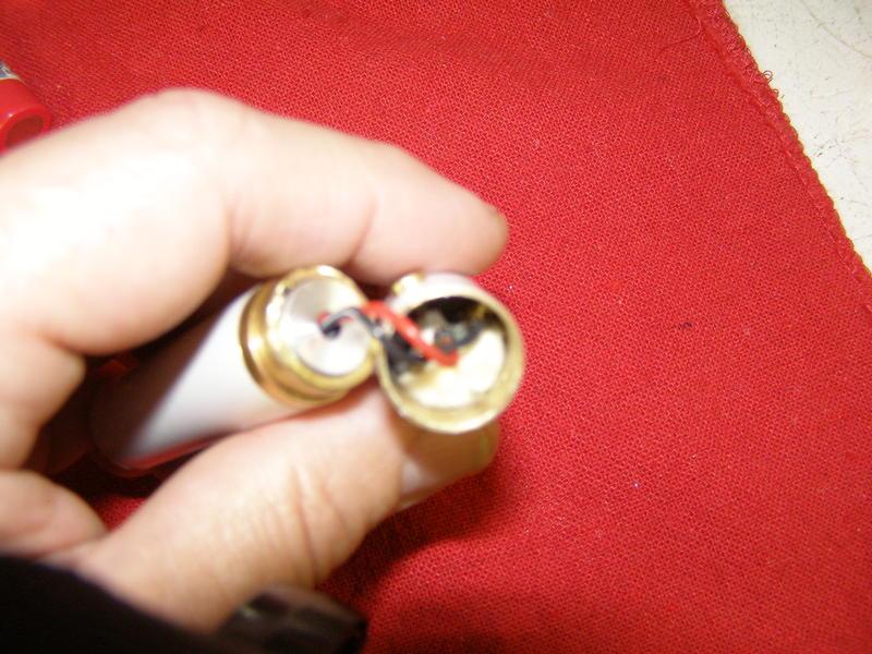
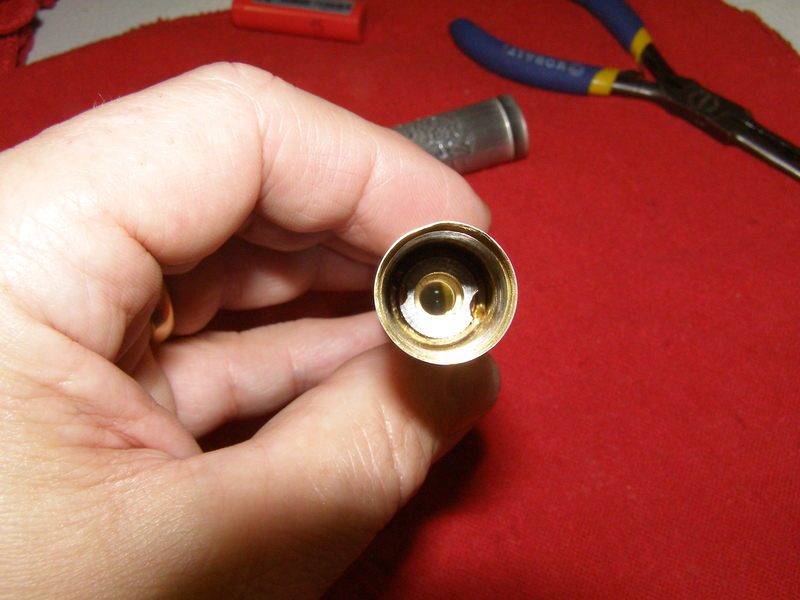
This is a cruddy pic but it's just showing the module that I pressed in and the final hookups. For a change, I bought the complete module with driver and G2 lens from DTR so nothing to show for putting the module together because I didn't do it. I did have to smooth out the inside of the heat sink to press it in:
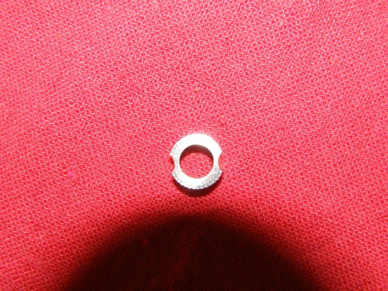
I cut a half moon into both sides of a lens holder so I could use my small long needle nose pliers to put the lens inside and adjust to infinity:
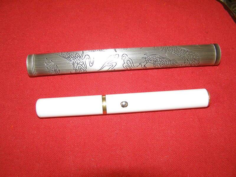
Some pics of the completed project. The funny thing is I had intended to store it in the dragon case that I bought off of Laser Chick that fit it like a glove but I forgot about the button sticking out. I could actually press it in but my bet is I might end up ruining the button so no dice on that. The button didn't end up staying silver as this pic shows:
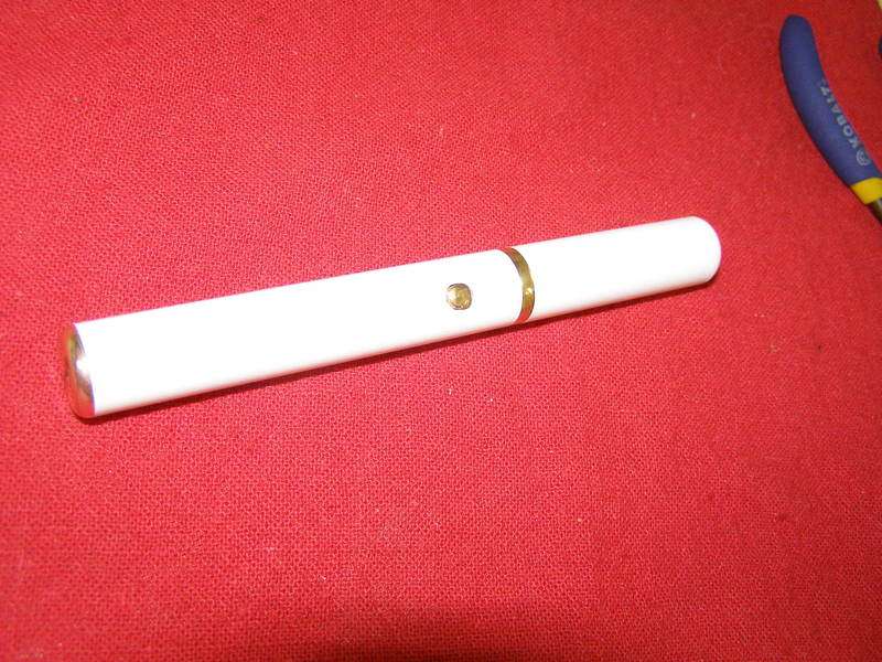
Pic with the button painted gold:
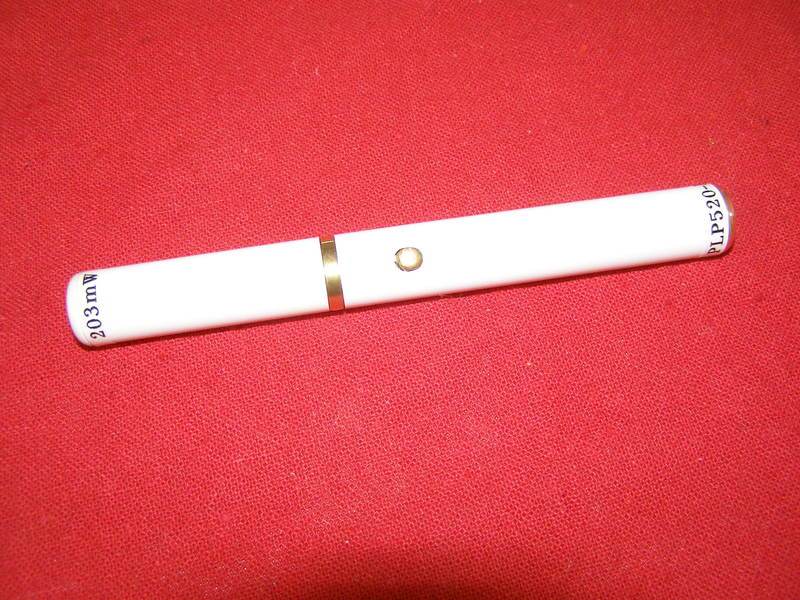
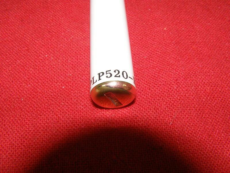
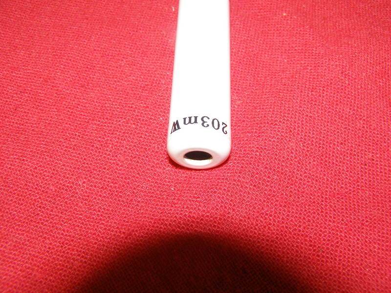
Like I said earlier it is running off a single 14500 and outputting 203mW with a G2. I had selected Jordan's max setting of 450mA but I can't remember if I tweaked the output or not as I built so many other units. I have a habit of pushing things beyond what he will sell his set to
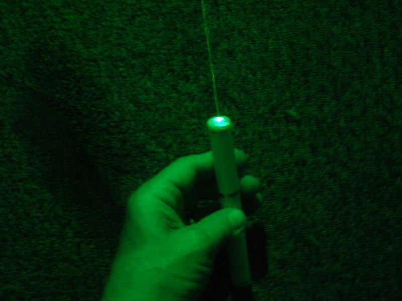
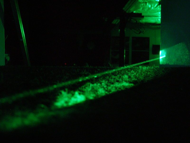
Some beam shots. My apologies as they are not very good:
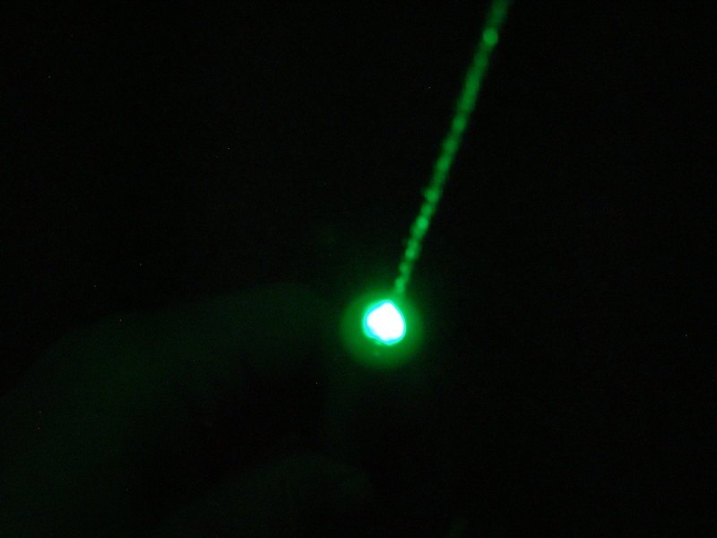
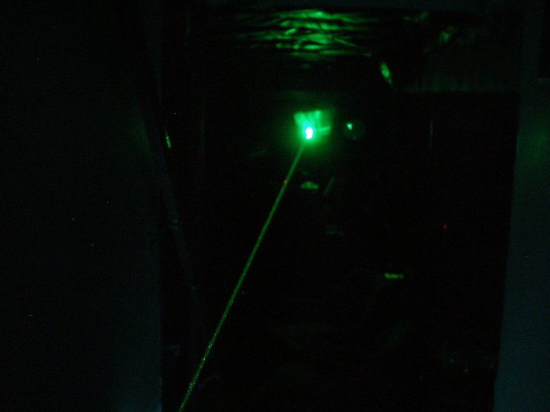
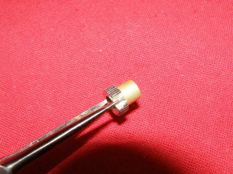
I realize I don't really show it but the top of the unit is screwed in so I could make a piece that bridges the gap between the lens holder and the cap so that I could focus it using the threads but for now I'm thinking of leaving it as is instead of doing what I do to make regular Ebay over-spec pens fully focus-able.
It took me quite awhile to decide what to put in it as I wanted it to be special because the host is special. I CAN make it focus-able if I want to but for now haven't. I'll explain that as I go along.
I forgot to take a pic of the host with nothing in it before starting the build so my apologies. It's not like you wont be able to follow along anyways.
One of the parts it came with was this spacer that had a spring on the end. I added the red wire to it:

There was already a hole going through it so I just fed the wire. What it doesn't show is I had to trim the whole plastic/nylon piece a bit on the back side where the switch is going to go so that it would line up with the host hole:

In order to fit the switch correctly I drilled a small hole at an angle for the negative wire:

The reason why I fed the negative wire through that piece is to make a way for the drive to catch the negative off the host wall just as I've figured out to do with all my laser66 builds (and there's a bunch finished I haven't shared yet


Soldered the negative wire to the copper:

Trimmed down this is what it actually looks like:

After removing all the components on the switch/driver and checking my options of where to solder the other end of the negative wire to this is what I ended up with:

I then soldered the + to the other side of the switch:


Looking down one end of the top section you can see there is a brass piece in there for a module to be pressed into:

This is the other end and it sticks out so the back half can press into it snuggly. All the scrapes were there when I got it and my guess is that something drastic had to be done to remove the innards:

I had to trim the end down a bit so everything would fit properly. Please keep in mind that I only have hand tools lol:

What you see here is the back half with the switch pressed into place:


Something of interest is I ended up having to change out the switch (just the actual small switch part on the board) and because of how this piece fit I needed to trim down the rubber boot that was supposed to slip inside over the button but while I was slimming it down with my dremel it flung off to parts unknown to never be seen again so I also modified for a different button to stick through the hole.
This is a cruddy pic but it's just showing the module that I pressed in and the final hookups. For a change, I bought the complete module with driver and G2 lens from DTR so nothing to show for putting the module together because I didn't do it. I did have to smooth out the inside of the heat sink to press it in:

I cut a half moon into both sides of a lens holder so I could use my small long needle nose pliers to put the lens inside and adjust to infinity:


Some pics of the completed project. The funny thing is I had intended to store it in the dragon case that I bought off of Laser Chick that fit it like a glove but I forgot about the button sticking out. I could actually press it in but my bet is I might end up ruining the button so no dice on that. The button didn't end up staying silver as this pic shows:

Pic with the button painted gold:

Like I said earlier it is running off a single 14500 and outputting 203mW with a G2. I had selected Jordan's max setting of 450mA but I can't remember if I tweaked the output or not as I built so many other units. I have a habit of pushing things beyond what he will sell his set to


Some beam shots. My apologies as they are not very good:


I realize I don't really show it but the top of the unit is screwed in so I could make a piece that bridges the gap between the lens holder and the cap so that I could focus it using the threads but for now I'm thinking of leaving it as is instead of doing what I do to make regular Ebay over-spec pens fully focus-able.
Last edited:


