Welcome to Laser Pointer Forums - discuss green laser pointers, blue laser pointers, and all types of lasers

LPF Donation via Stripe | LPF Donation - Other Methods

Links below open in new window

ArcticMyst Security by Avery

Sound card DAC tutorial

Joined
Jul 22, 2008
Messages
288
Points
28
if i've read corrctly... 1 sound card, and 1 correction amp are needed? or is it one set per galvo equalling 2 sound cards and 2 correction amps?

michael

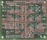
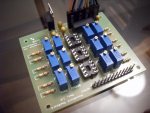
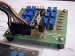
Just 1 sound card and 1 correction amp is needed. I plan to permanently mount my correction amp on top of the sound card using "stand-offs" I purchased from radio shack. The correction amp controls several things: X & Y galvos (2 connections), the brightness of up to 3 lasers (for RGB) and the last connection can be used for anything else (like a safety shutter).

NOTE: My SpaceLas 30K galvos just came in the mail today, super fast shipping :)
 
Last edited:


Joined
Dec 23, 2008
Messages
3,948
Points
63
thanks. i just ordered the bare pc board. and will pick up as many parts as i can at my local electronics store.

michael
 
Joined
Jul 22, 2008
Messages
288
Points
28
I just got my "LaserBoy" correction amp in the mail from Dr. Lava. A couple people requested that I scan and upload photos of the bare PC board. Here you go :)

I had to scale down the attached photos to upload to LPF. The full resolution scans are on my personal website...

Full resolution scans here:
http://zimmtech.net/LaserBoy1.jpg
http://zimmtech.net/LaserBoy2.jpg
 

Attachments

  • LaserBoy1b.jpg
    LaserBoy1b.jpg
    126 KB · Views: 710
  • LaserBoy2b.jpg
    LaserBoy2b.jpg
    103.3 KB · Views: 661
  • LM7905b.jpg
    LM7905b.jpg
    49.3 KB · Views: 611
  • Completed.jpg
    Completed.jpg
    73 KB · Views: 669
Last edited:
Joined
Apr 2, 2009
Messages
355
Points
0
I think the LM7905 you depict as having a "metal tab" is the TO-220 package. It will not fit through the holes on the board (on mine anyway), so you will need to solder it to the bottom or solder small pins to the chip and solder those to the board. I will try and post a few pics of my completed amp and DAC.
 

Benm

0
Joined
Aug 16, 2007
Messages
7,896
Points
113
Interesting scans.. here is an "x-ray" view from the top side for those that want to reproduce this correction amp. It seems very close to the designs i posted, but it has the power source from the USB included, which is nice if you want a usb-to-ilda box :)
 

Attachments

  • coramp-lava.jpg
    coramp-lava.jpg
    200.4 KB · Views: 594
Joined
Jul 22, 2008
Messages
288
Points
28
I think the LM7905 you depict as having a "metal tab" is the TO-220 package. It will not fit through the holes on the board (on mine anyway), so you will need to solder it to the bottom or solder small pins to the chip and solder those to the board. I will try and post a few pics of my completed amp and DAC.

Thanks for the tip friend! This is the exact LM7905 I ordered online and it should be here this week:
LM7905CT Fairchild Semiconductor Linear Regulators - Standard

I will take you advice and solder pins onto the PC board. You think the part I got will work? I am not an electronics expert so any help is much appreciated...
 
Last edited:
Joined
Apr 2, 2009
Messages
355
Points
0
Actually I found another way to get it to fit. If you take a sharp knife and gently scrape away at the pins you can shave them down enough to fit into the holes on the board. Then the part can be soldered on normally. Just be careful not to cut the leads or yourself.

Edit: I will be tuning my DAC sometime this week and posting back with the results.
 
Last edited:
Joined
Apr 2, 2009
Messages
355
Points
0
So in attempting to tune my amp, I am unable to get the voltage to 0 using the offset pot. I am using a 50kohm pot as recommended by drlava. The pot is maxed out in 1 direction and the voltage is staying at around 1.7 to 2 volts depending on the channel. has anyone else had this problem or know how to fix it?
 

Benm

0
Joined
Aug 16, 2007
Messages
7,896
Points
113
To which direction did you max out the pot? At a quick glance it would be worthwhile to adjsust gain before offset with these correction amps. Try setting gain to maximum, then adjust offset, and finally reduce gain to fit your needs.

If it doest work out, you can build the schematics i posted from basically the same components, with a bit of scaling.
 
Joined
Apr 2, 2009
Messages
355
Points
0
I tried what you recommended, but still no success. I did however notice this: On the OP it says to solder the wire to the positive lead on the cap, which is the one farther away from the output jacks on the sound card. However on my sound card the caps are reversed; the lead is the one that is closer to the jack. I still soldered to the positive lead, but could the fact that now the signal is going through the capacitor instead of bypassing it be the problem?
 

Benm

0
Joined
Aug 16, 2007
Messages
7,896
Points
113
Yes, you must solder it to the lead of the capacitor that is connected to the chip, not the one that is connected to the output jack.

It would seem odd to have an output coupling cap with the positive end towards the jack though - so it must be installed wrong, or wired differently (post some pics of the board, top and bottom).
 
Joined
Jul 22, 2008
Messages
288
Points
28
Yes, please post photos of the top and bottom of the C-Media soundcard. That is about the only component I am waiting for and then my RRGB projector will be complete! It should be here next week and it would be nice to know where to solder the leads in advance.

FYI - I finished soldering all the components onto my correction amp the other night. If you look at the attached photos, you will see that I used an old PC ribbon cable that will go from the correction amp to the sound card. Should be nice and clean when everything is done :)
 

Attachments

  • LaserBoy1z.jpg
    LaserBoy1z.jpg
    88 KB · Views: 574
  • LaserBoy2z.jpg
    LaserBoy2z.jpg
    77.5 KB · Views: 468
Last edited:
Joined
Nov 7, 2008
Messages
5,725
Points
0
I tried what you recommended, but still no success. I did however notice this: On the OP it says to solder the wire to the positive lead on the cap, which is the one farther away from the output jacks on the sound card. However on my sound card the caps are reversed; the lead is the one that is closer to the jack. I still soldered to the positive lead, but could the fact that now the signal is going through the capacitor instead of bypassing it be the problem?

Are you using the c-media card as in the tutorial? If so, then the positive side should be the same as in the OP, unless you have some newer revision. Also, just to clarify, the positive side of an electrolytic capacitor is the unmarked side. Only the negative side is designated.
 
Joined
Sep 4, 2010
Messages
57
Points
8
hi

could u bias one of the op amp inputs (the grounded one) below the -v peek from the sound cards output, so u dont need to mod it? ie the differential gain is always positive?

apologises if this is incorrect, im still learning this stuff.
 
Joined
Apr 2, 2009
Messages
355
Points
0
Yes I have a cmedia card but its a little different. Its square and not L shaped, and has fewer DACs
 

Benm

0
Joined
Aug 16, 2007
Messages
7,896
Points
113
Well, you can also just short out the capacitors, soldering the wire to the correction amp to both its leads. As long as you dont insert anything into the jack, it will not make a difference.


Top