Welcome to Laser Pointer Forums - discuss green laser pointers, blue laser pointers, and all types of lasers

LPF Donation via Stripe | LPF Donation - Other Methods

Links below open in new window

ArcticMyst Security by Avery

Sound card DAC tutorial

Benm

0
Joined
Aug 16, 2007
Messages
7,896
Points
113
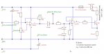
Additional schematic: From soundcard dac to laser diode: the driver.

This doesnt conform to ilda standard, but it allows analog modulation of a laser diode direcly from a dc-modded soundcard. Rsense should be chosen for 1.2 volts at maximum desired current (e.g. 4 ohms for 300 mA etc).

Adjustment is fairly straightforward: first adjust the threshold pot to where the lasers starts to come on, then take it slightly below that point. Next adjust gain to result in 5 volt signals on the testpoint using a scope. The two 1n4148 diodes prevent you from overdriving the laser diode by mis-adjustment, so it can be safely done without a scope too by just eyeballing brightness.
 

Attachments

  • dac-laser-driver.jpg
    dac-laser-driver.jpg
    52.5 KB · Views: 6,620
  • Like
Reactions: ped


Benm

0
Joined
Aug 16, 2007
Messages
7,896
Points
113
PS: you may need to configure your software for 'inverted blanking'. As drawn, a positive signal will turn the laser off (i.e. blank it). You can use the second half of the TL082 to build an inverting amp if you want to alter this issue in hardware.
 

ReNNo

0
Joined
Mar 27, 2009
Messages
589
Points
0
Thank Benm.
I had lot of dilemmas about driver with analog modulation. Now I know that this is confirmed that works, thanks.

+1 Rep
 

Benm

0
Joined
Aug 16, 2007
Messages
7,896
Points
113
I had some prolems with them myself, but this seems to be the easiest solution.

It does bypass the ILDA standard signals, going directly from the soundcard dac to the laser diode, but that saves a bit on component count.

For those who require more precision, the 2 in 4148 diodes used as a voltage reference can be replaced by a 1.25 volt bandgap reference. Personally i like the diodes as references, since they drop the current a bit if things run really hot. Its by no means a foolproof protection mecanism, but at least it responds in the correct direction, preventing thermal runaway.
 

ReNNo

0
Joined
Mar 27, 2009
Messages
589
Points
0
Hey Benm, I sent you a few personal messages, can you take a look in your inbox.
You can answer it here...

I see that you included 12V power supply just where LD is.
Why did you include another 12V voltage supply if this "rail" is connected to 12V source?
 

Benm

0
Joined
Aug 16, 2007
Messages
7,896
Points
113
About Renno's questions and to clarify some things about the latest schematic:

I've simplified it for your convenience by replacing a potentiometer by a fixed resistor.

In the real world circuit, the 10k resistor between the CA3140 positive input and ground is a 10k potmeter, with its slider connected to the opamp input.

With this approach, its easy to set maximum current using a low power potmeter: Just configure Rsense for the absolute maximum you want to be able to output - i'd suggest 2 ohms for a maximum of 600 mA.

Using the potmeter you can then set the operation maximum current to whatever value below that by adjusting the potmeter. If you were to use 2 ohms as the sense resistor, the maximum current would be 600 mA, but if you turn down the potmeter to 2/3rds, it would be 400 mA.

I made this simplification to match the current calculation with the wellknown DDL current sources, but it can be made adjustable by one simple replacement. I suggest replacing the 10k resistor with a pot if you want something adjustable: putting a pot in the sense path would require the pot to take a lot of current (i.e. the full laser current) which could be problematic.
 

ReNNo

0
Joined
Mar 27, 2009
Messages
589
Points
0
Yes, that is what I wanted, to set desired current with low power potentiometer, thanks.

But can you answer me first question?

I see that you included 12V power supply just where LD is.
Why did you include another 12V voltage supply if this "rail" is connected to 12V source?
 

Benm

0
Joined
Aug 16, 2007
Messages
7,896
Points
113
Oh, i drew a jumper there: You can run the laser diode from a seperate power supply if the +/- 12v one doesnt supply enough current. The driver needs about 2 to 3 volts excess voltage to work, so you can run reds and greens from a much lower external suplly - something like 6 volts. This way the BD139 doesn't get as hot, and you waste less power overall. For a bluray or 445 the external supply should be a bit higher, about 8 volts would suffice.

Using an external supply for the diodes also prevents them from pulling the primary power supply down. With 2 or 3 colors installed, you can get current draws of over 1 amp - not all supplies are well regulated enough to keep the voltage constant.
 

ReNNo

0
Joined
Mar 27, 2009
Messages
589
Points
0
I plan to use single computer PSU that can give 10A on 12V rail.
And want to use 12V only.

I know that BD139 is going to be very hot but I'm going to use big heatsinks that will be cooled by fans.
 

Benm

0
Joined
Aug 16, 2007
Messages
7,896
Points
113
What kind of lasers are you planning to use?

Powerful greens might pose a problem at 12 volts - if they require something like 700 mA to operate, the transistor will dissipate up to about 6 watts for that channel. It can handle that just fine, but it would obviously need a sizeable heatsink to do the job.

I prefer to keep things below boiling point, so a 10K/W or bigger heatsink would be required.

If you want to use the 12 volt supply, i would recommend using a bunch of 540x diodes in place of the drawn jumper to pre-lower the voltage and spare the transistor a bit.

I've got this setup working with a red and green laser, both taking about 350 mA, and the transistors get seriously hot running off 12 volts when turned on continously.
 

ReNNo

0
Joined
Mar 27, 2009
Messages
589
Points
0
Only problem would be green laser that is going to work on a about 500-600mA.

I plan to use 445nm diode and two red diodes in series.
These won't be problem.
Is there any way to power up green laser with 5V source?
 

Benm

0
Joined
Aug 16, 2007
Messages
7,896
Points
113
Sure - you have to build this circuit for each color, so you can use a 5 volt supply for the green one and the 12 volt for the others. If the 5 volt is not enough, you can remove the 1 ohm sense resistor, saving another 600 mV. Just use a mulitimeter in 10/20A range to adjust the desired current.
 

ReNNo

0
Joined
Mar 27, 2009
Messages
589
Points
0
I'd like to make PCB as simple as possible.
Another rail will make PCB more complicated.

I've just done a test on it...

DSC01335.jpg


It's LM317, input voltage 12V, output voltage 1.7V, current 625mA. (It simulates BD139)
That means that LM317 had to dissipate about 5.66W of heat.

You can see that heatsink is cooled with small 80mm fan and must say that chip isn't hot. (Measured 35C at chip after 10 minutes)

So, there won't be problems with heat.
 

HIMNL9

0
Joined
May 26, 2009
Messages
5,318
Points
0
.....
That means that LM317 had to dissipate about 5.66W of heat.

Yes, all the voltage that the regulator have to take out for keep the current stabilized, is dissipated in heat (BTW, 12 minus 1,7, multiplied 0,625, gives you 6,43W to dissipate ;)) ..... for this reason, is always better to use a power supply voltage that is the nearest possible to the needed one for the loads .....

I mean, if you need 2V for have the current that you want through the load, and the regulator itself drop other 2,2V, you need at least 4,5 / 4,7V, so, using 5V as input, the dissipation is reduced ..... same if you need 5V on the load (like a BR) the minimum input must be 7,5 / 7,7V, so a 9V power supply is ok .....

Or you can use an LM1117, that have 1,2V of internal dropout, so it dissipate less power itself, when the voltage that you need is near the maximum that you have (as example, if you need 3V, and the LM317 drop 2,2. you can't use 5V, need 9V if you don't have a 7,5V PSU, and this increase the heat, but with an LM1117, that drop just 1,2V, you can use the 5V and dissipate less in heat)
 
Joined
Apr 2, 2009
Messages
355
Points
0
Has anyone experimented with any other sound cards besides this one? I would like to get one of these, but since my host I ordered from DX has yet to arrive 4 months later, I am somewhat hesitant to spend any more money over there.
 
Joined
Nov 7, 2008
Messages
5,725
Points
0
ANY sound card will work, you just need to know where on the board the output capacitor is for each audio channel. This is sometimes straightforward and sometimes not depending on the card. The soundcard DAC uses DC signals so the decoupling caps need to be bypassed. The soundcard used in this tutorial has already been mapped out, so using it can help make the process simpler and less tedious. Here's the same card on ebay: New USB 6 Channel External Audio Sound Card S/PDIF PC - eBay (item 280503843373 end time Oct-05-10 03:12:00 PDT)
 
Last edited:


Top