- Joined
- Nov 7, 2008
- Messages
- 5,725
- Points
- 0
^It's a standard feature in every program that supports the soundcard DAC..


Follow along with the video below to see how to install our site as a web app on your home screen.
Note: This feature may not be available in some browsers.


Hello Folks!
I have a 6ch CMedia ready and want to build an quick & dirty correction board.
Could you help me?
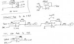
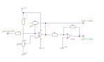
I drawed a plan with the patient help of Nicolas (weartronics) and his great Differential Amp Design. As i cant get the ±9V DC Converter here, only 5 to ±12V, which wont get enought power from usb; i thought of taking one of the 12V wallwarts i have colleting dust, and creating ±5V from it by splitting regulated 10V. the dropout of the IC is 2V so it fits, or not?
Also, i have a only TTL modulated Laser (Pf-114) so i dont need real linear amplifying by now, it should just be able to blank the Laser with Spaghetti and HE. Maybe someone could give me a solution that uses only Transistors for the RGB chan or even raw unamped Soundcard Output.
Here are the input specs: Bild: 300mw_rgb_animation_lao40c.jpg - abload.de
Sorry im a total noob in Electronics. i can solder even SMD without problems but have no clue how the stuff works and how to design a circuit from scratch and what parts i need etc...
Thanks
TC