Welcome to Laser Pointer Forums - discuss green laser pointers, blue laser pointers, and all types of lasers

Buy Site Supporter Role (remove some ads) | LPF Donations

Links below open in new window

FrozenGate by Avery

Sale Thread: New Inexpensive 18650/cr123a Host Kit - $25 Shipped!

Brad I recieved my package this morning. Thess hosts and heatsinks look better in person than the pictures from the OP. I've been offline all day & can't share my own pictures right now, but I will when I'm back in my lab.

Until then, I just wanted to thank you again for taking the time, interest and effort with making these. I know this wasn't a simple, straightforward nor 'problem free' procedure, but if you do decide to get back into hostmaking anytime soon - - you most certainly have my support! :D

I can't wait to make a few builds from these & share the outcome with the forum :beer:

Good to hear! I will be making more kits or different varieties once I get some more free time.

hey helios is my reservation for one of these gone. sorry its been a while since i checked back with you or this thread but car trouble plus other builds got in the way as i was waiting for these. I finished all the above and have 25 bucks to spare so i was wondering if i could FINALLY pick up one of these great hosts. (depending on availability.)

Availability of these is 0 until I can fix my mill unfortunately. Once I do and get some kits finished I will start offering them to those who were interested on this thread first.


Hey man, got my host saturday -8:00 gmt and I must say, these are well worth over 30$.....great hosts!!!
 
^ Indeed. They're solid, sturdy and should be very easy to work with :D

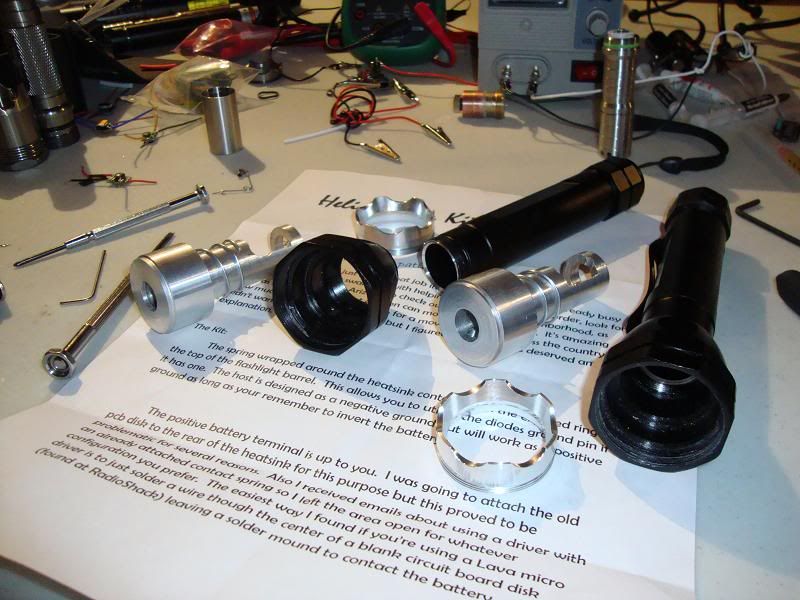
DSC08143.jpg


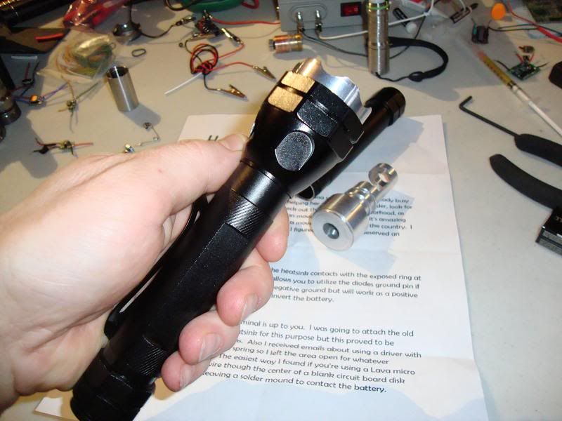
DSC08145.jpg
 
I have a general question for anyone who has received their Helios kits and might've started their builds with it. I'm trying to find the best option for using a battery contact board w/ Brad's heatsink and I'm curious if anyone has a good solution/answer.

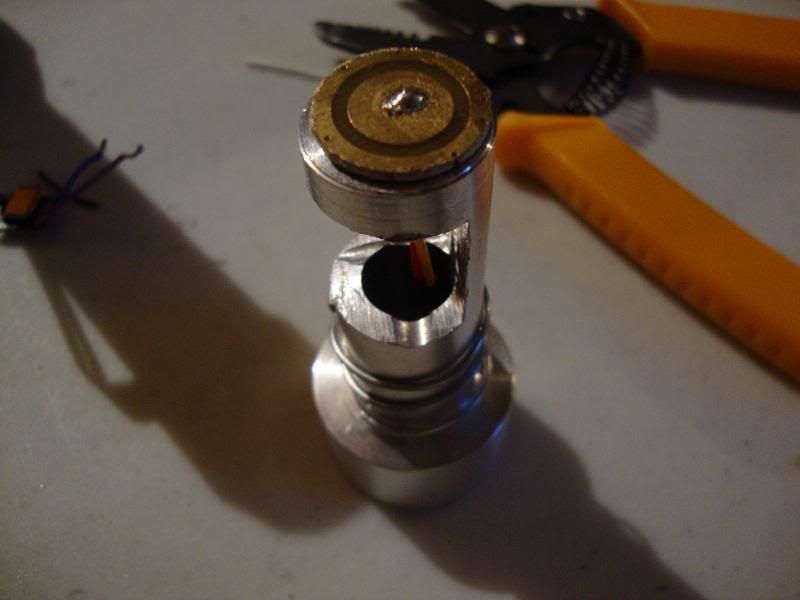
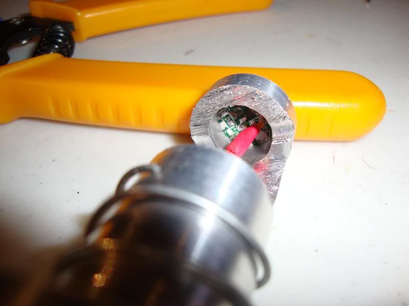
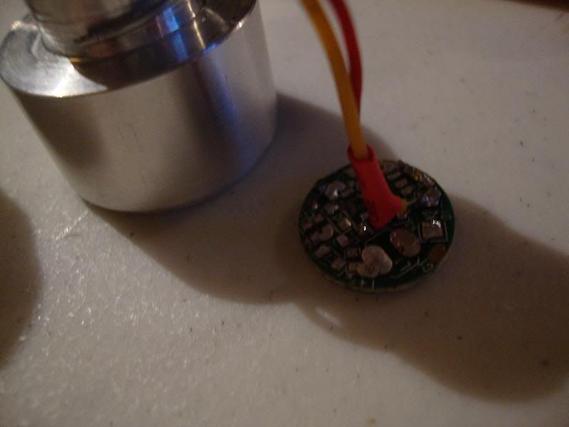
I stripped a generic chinese cheapy driver of all it's components to experiment on how it could mount to the heatsink....

DSC08177.jpg


Side view, unbonded

DSC08178.jpg


Front view

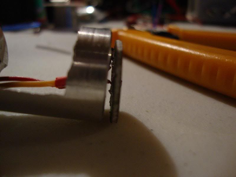
DSC08179.jpg


Mounting side of driver (opposite of battery contact)

DSC08181.jpg


Because the mounting side of the driver isn't perfectly smooth for a flat bond and also has an elevated solder blob near the edge from the battery negative lead, I was thinking of bonding a couple of tiny 'feet' along the edge of the board to bond to the heatsink. It's probably not the best way to mount this, so again I'm just curious if anyone else has done or thought of something that hasn't crossed my mind yet.
 
Thats exactly what I ran into when using the led driver. I suggested in the instructions using a blank PCB piece or get out the soldering iron and take off all those components. Then to ensure it is isolated from the host ground apply a thin layer of epoxy to the board and let it dry before you epoxy it on with more. This will ensure there are no shorts.


This is the blank board I am referring to

images


it can be found at any radioshack and then you can just cut it into a disk and have plenty to spare for future projects!
 
Last edited:
Ahh nice ok, I'll pick some up today & follow your example Brad :D

BTW I was planning on not using the diode case pin & grounding the negative lead from the battery to the driver by soldering it to the heatsink from the battery contact board. Do you think that's a bad idea? I've been a little confused about whether or not to do this from problems with a previous build testing fine, but not working when assembled. :thinking:

you will have a problem soldering to aluminum...its practically impossible. It might be easier to solder the neg driver input to the ground pin on the diode and then wiring up both of the driver outputs to the other pins.

If this sounds confusing it is until you see it. Search through some of DTRs build threads as he usually sets up his this way. Otherwise you could drill and tap a small hole for a machine screw to cinch down a ground wire.
 
Last edited:
Hey Brad. I'm pretty bummed I didn't get in on this... If you make another round list me for one.

Thanks,
Ben
 
It might be easier to solder the neg driver input to the ground pin on the diode and then wiring up both of the driver outputs to the other pins.

Doing that would bypass needing to contact the heatsink & driver neg input? I was not aware of this :beer: Per my planning I have the neg driver input wrapped around the side of the battery contact, which pinches it between the contact itself & the aluminum when mounted. It seems to do to trick for accomplishing the connection, but I'm always looking for a better or more stable way of doing this.

If this sounds confusing it is until you see it. Search through some of DTRs build threads as he usually sets up his this way. Otherwise you could drill and tap a small hole for a machine screw to cinch down a ground wire.

Indeed. DTR's threads & tutorials (like Jayrobs) are priceless to me, I reference them all the time. I hadn't thought of tapping the heatsink for setting a mounting screw, that's also a good idea. Thank you good sir!
 
Doing that would bypass needing to contact the heatsink & driver neg input?

Since the ground pin is part of the diodes external package it is part of the ground so you can use it as the driver ground. (this all assuming the diode is a 445nm or similar configuration) This is what I do if space allows and in this case you have all the space you could ever want.

No problem. If you have any more questions feel free to ask.

It does follow the 405/445 configuration, yes. Thank you for making that clear to me also, I honestly hadn't put much of any thought before with using the case pin as a grounding option like this :D
 
Aaaargh! The postman dropped a notice for a package from some dude named "Brad".:whistle:
Can't wait to pick it up tomorrow!:drool:
 
Yea I hate that so much. Waiting knowing its their waiting for you and you could have already had it.
 
I got two lasers, a few other things just sitting 70 miles away at home, Stuck on the rig though.. :(
Is he up and running again?
Love to get me hands on one of those great host..

RDCII
 
Put me down for one please, roughly what would you be wanting extra for it to be sent to Australia?


Back
Top