Welcome to Laser Pointer Forums - discuss green laser pointers, blue laser pointers, and all types of lasers

Buy Site Supporter Role (remove some ads) | LPF Donations

Links below open in new window

FrozenGate by Avery

RF excited CO2 lasers

Event Horizon: UM... It is possible that those heat sinks are messing with the tuning of the laser tube. and that could have something to do with the problems you have had with your laser. I just thought I would point that out, I could be wrong though.  ::)


P.S. My co2 laser bot is almost done! :D


Disma ---

There are at least three power supplies on this sale. I can't help many because of differences between mine and there's. Have you powered up ?? Which supply do you have?? You may have key info here to help others.

Mike
 
Disma, I am pretty sure they aren't the problem, as there is literally no output from the RF supply. But I admit I didn't consider that as a possibility. I'll try taking them off and seeing if that solves the problem.

EDIT:

I popped the heatsinks off and still no change. Well at least that's one less thing on the list.
 
Alright, I received a second RF supply board from nightstick. Hooked it up in exactly the same way that I hooked up the original when it was working, and STILL THE SAME PROBLEM. I get the little MOD OK led, but the RF OK light stays off. No lasing output, no heat from the power transistor, no current draw the 5V supply and little current draw from the 12V and 32V supplies. I double checked my connections and everything is fine.

So I guess now the problem MUST be on the laser head. Continuity tests check out so the only thing it can be is the FET. Chris said the things are really durable but I can't imagine what else it could be! I'm starting to get very frustrated with this, nothing makes sense to me anymore.

So, how to I test a FET? The same way as the power transistor?
 
It's like a tube  -- High impedance input to the gate (grid)  I think the gate should look open with the ohm meter but I forget some of this.  
See your PM.

Mike
 
Sorry to hear the new amp didn't solve your problem EH. :( Just keep the spirit high and I know you'll fix it in the end!

My laser is in the test bench. It gets pretty hot though. Got a new compressor to cool the lasertube but it still climbs up to about 50 degrees C (about 120degF) after about 15 min on 90% duty-cycle. Is this acceptable or what? I have no idea which temps are OK for these tubes and I also have no idea about where to find info regarding this issue.
Does it sound OK to you guys?

I'm assuming that the amp-board will have sufficient cooling from the two 120mm fans I gave 'em.

Regards
/Tottish
 
The laser I have now (gave the other one away for a Christmas present) has the single voltage power supply. The other one I gave a good friend for Christmas has the multi voltage input supply, and I had a lot of problems getting that one to work, it turned out to be the big fet on the laser itself. When you disconnect the main board from the laser tube, the rf led on the board came on for me, but when it was connected to the laser tube, the led didn't light up.  :)
 
Disma, where did you get a replacement FET? Maybe I got two bad RF boards though, because I still don't get the RF light even when the laser head is not connected. This is on both of them. So it would seem as if the signal is not making it to the output of the device. The power transistor stays cold so the problem must lie somewhere before that. I'll have to get that oscilloscope then.
 
Chris sent me a replacement, he is right about them being really heavy duty parts, I am surprised that this fet was bad, they are rated way over what you would think they are rated for, but it was still bad. I looked around and couldnt find one anywhere else. :) I am willing to bet you dont have two bad boards, although it is possible, you need to test it with an oscilloscope.
 
Well unless I got two bad board the FET must be bad. I'll contact Chris to see if he has any more. It's the only active component on the laser other than the caps which seem to be good.
 
EH --- Maybe I didn't notice but are you drawing ~ 20 mA on the PWM input ??

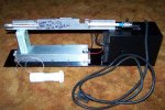
I'm starting my CO2 labbie powered by a 28 volt PS all mounted to a 1/4" alum plate. The white thing is the beam expander ready to go.

Mike
 

Attachments

  • CO2-11.jpg
    CO2-11.jpg
    26.5 KB · Views: 1,382
Yes, the PWM input is drawing about 25mA. It's the 5V input on the board that is drawing zero. I should have that oscilloscope this week sometime so expect more confused questions soon!  ;D

Your build looks pretty nice Mike, I bet it's going to look real nice once it's done! Question though, where did you get a diverging optic for your beam expander? I see converging lenses all the time on ebay but I've never seen a diverging lens.
 
I got one from ebay -- unknown neg FL --  Double concave.  I haven't tried it yet but it's mounted in the expander in the picture.

I also found a few stock over runs of 1/2" Dia x -1.39" FL x AR coated for 10,600 nM.  Those were $54 plus shipping to me.  I've sent one to Lynn (NightStick) for his laser.  These are what I'm using in my 3.5x and 5x expanders.  If you need one, let me know.

Mike
 
I am afraid they are all gone.

I got my oscilloscope today but I am overloaded with schoolwork so it might be a while before I make any progress.


Back
Top