Welcome to Laser Pointer Forums - discuss green laser pointers, blue laser pointers, and all types of lasers

Buy Site Supporter Role (remove some ads) | LPF Donations

Links below open in new window

FrozenGate by Avery

Raman-spectroscopy

It looks pretty good, Bernd. I hope it works out for you the way you are expecting it to. I'll be interested in any updates you might have to this.


ha, just stumbled upon this thread. i worked with a raman spectroscope during my B.Sc thesis to verify crystallisation of germanium probes after a laser process. was kinda fun looking at those peaks :D
 
Hello,

for a complete redesign of an optical assembly to use my existing components I looked around for affordable components pretty intensively. The technically most suitable solutions for this are in principle such cubes, as you get for example from Thorlabs.

Link: https://www.thorlabs.com/thorproduct.cfm?partnumber=LC6W

These cube cubes cost already 125,17 € and that without additional attachments. This is much too expensive for home improvement for hobby purposes (for me). While surfing the internet, I found several open source projects and decided on a 3D printing solution. So I am quite flexible and can also use my own non-standard components.

I liked the approach "frame for 3D-printable optomechanics" by Mihails Delmans and Jim Haseloff.
Here are some descriptions on the internet, for example:

Link: https://openhardware.metajnl.com/articles/10.5334/joh.8/
Link: https://www.hackster.io/delmans/ucameracube-c64263
Link: https://mdelmans.github.io/uCube/
Link: https://github.com/mdelmans

I took up these ideas and the corresponding framework and modified and expanded accordingly.


Here is the description of the basic cubes, later different filters and optics are adjusted here:

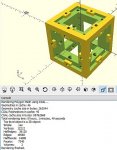
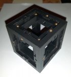
I scaled this "cube" body to 30mm inside with Openscad in the first step, this is then 58 mm outside; the 1 inch filters are just the right size and printing time is minimized.

1 CAD.jpg

Openscad is a script-based design language. Here you can integrate libraries that contain different routines. Own modifications and constructions are also easily realizable and therefore ideal for the home improvement. After rendering, the 3D model is now ported as *.stl and can be converted into a printable file in a slicer. I used Ultimaker Cura for that.

Due to the high resolution of 0.1mm layer thickness and the creation of the carrier, the print takes a little longer. Support also has drawbacks because these support structures take time and potentially disruptive elements may occur, but here you are in spite of other description in the ucube project necessary. Otherwise, the upper cantilevered structures can not be printed in the desired size.

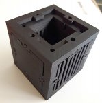
After about 13 hours of printing, the finished cube has about 64g, costs 94 cents of material and the inclusion of the above support structures looks like this:

3.jpg

After removing these internal structures, one recognizes residues that do not interfere technically.

4.jpg

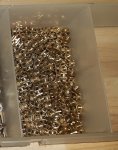
Now brass M3 threaded inserts are inserted into advanced holes. For this I have heated a soldering iron to 250°C and slowly inserted these threaded inserts.

6.jpg

7.jpg


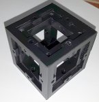
On each of the 6 sides, there are now 4 threaded inserts for attaching the outer surfaces, which can accommodate various optical components or other functions. In addition, there are 2 more threaded inserts and 2 holes on each side. Here further cubes can be screwed to a super cube array or other functional parts.

8.jpg

I will describe the other add-on parts gradually over the next few days, because, as you know, such a description and documentation is quite a work.

greeting

Bernd
 
That was an interesting read. It took awhile to go through all of it, but I see how you managed to print the Ucube and add the brass threaded inserts to each side. Nice job getting this done to scale. Thanks for sharing it here too.
 
Hello,

In the next step, I created the central component, the beam splitter.
For this I have adapted an element from the already described library according to the dimensions of the existing dichro splitter.
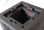
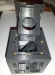
In principle, it is the lower of the six side walls with a 45 ° vertical inward holder, placing this round dichro exactly in the middle of the cubus.
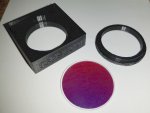
The dielectrically coated and reflecting surface lies exactly in the cube diagunal and an additional printed ring holds the filter in this socket.
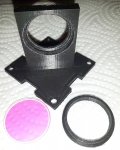
1.jpg

The sepcial optical properties of this dichro can already be recognized by comparing reflected light and transmitted light.
In incident light is red and in transmitted light as the function is green.
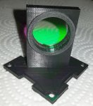
2.jpg


I bought the filter in the ebayshop from the already named distributor bjomejag, here you get filters of all kinds from the product range of omega optics at fair prices. These often come from overproductions and are therefore affordable for hobby buyers. For many of you certainly interesting, this company is in the US .... I had to pay the corresponding duty.

The dichro described here is according to the original description:
"Optical Filter Dichroic 540DRLP 25mm dia X 1mm Beam Splitter @ 45 R95% @ 532nm.
This filter is NOS from Omega Microscopy line.
The filter seperate a band of Green by reflecting it at the right angles to the incidence light,
while transmitting nearly all the Green / Yellow and Red above 550nm.
The filter is ideal for use with a 532 Laser with 95% + R in the S plane,
and 70% in the P plane.
Transmission of 555 to 700 nm in the plane is very efficient.
(Optimized for the S plane polarization in reflection).
The filter makes a very good epi-illuminator of Green excitation,
onto a sample, where the emitted light is retro-transmitted through this filter.
filthe specifications follow:
Reflection band 475 to 540 with average of 90.9%,
Transmission band 550 to 750 nm with an average of 90%,
Size 25 mm 1mm thick, Substate material is Borosilica glass.
Original cost $ 150 "

BUT .... I got this for net US $ 29.50 ++.
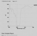
dichro.jpg

From below, this dichro holder sidewall is now inserted into the cube and attached to the cube with four countersunk screws DIN 965 stainless steel V2A TORX M3 x 16 mm.
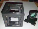
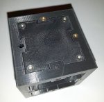
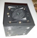
3.jpg
4.jpg

The later mounted laser hits this dichro and is polarized reflected in 90 °, the 532nm used here meets with about 300 mw through an objetiv (description follows later) on the medium to be examined and then as a reflection along with the emulated raman stroke and antistroke
again on this dichro, here again 50% of the now unwanted 532nm are discharged and the desired signal is left.
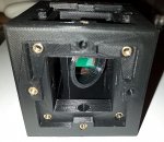
5.jpg

The dimensions of the vertical 45 ° dichro holder I then designed so that I still have some space for another component between this holder and the cubus inner wall 30x30mm ... (will follow)
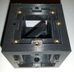
6.jpg

The next component described will be the side wall with the lens holder.

greeting

Bernd

PS.: I hope me englisch is not to bad ......
 
Nice snag on the dichro filter. Your English is not too bad as I was able to figure out everything you were trying to say. Thanks again for sharing your project here as I am considering trying to make one of these in the future and these ideas are definitely helpful. (y)
 
Hello,

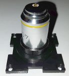
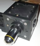
next here is the description of the side wall with microscope objetiv,
this time with a little less words ....

2.jpg

The objective 40/0.65 is quite simple, I bought it on ebay for less 10.00 Eur.

1.jpg

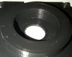
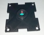
I printed this side wall directly with the RMS thread W 0.8 "× 1/36",
at first I was unsure whether the fine thread is printable.

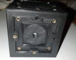
3.jpg

So the ojektiv actually pass a bit tight in this thread, depending on the used 3D printer it could be even a bit bigger created.

4.jpg

The side wall with objetiv will be mounted 90° to the laser entering behind the dichro and focuses the LASER on the object to be examined.

5.jpg

Raman shift (stroke + antistroke) then passes again through this lens in the opposite direction.
The dichro now filters out part of the unwanted 532nm 90° and the rest reaches the opposite side in the direction of the detector.

The next construction group follows ...

Greetings

Bernd
 
Hello everybody,

so that the time is not too long, here is still a small intermediate.
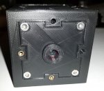
On one side the laser beam has to go in, depending on the quality of this one,
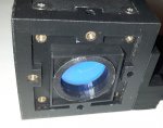
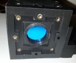
I have installed an IR filter in this side wall, which is simply held with a printed clamp ring.
The filter used in this case has a diameter of 9.5 mm and it is a cheap item from China for 0.5 Eur.

"The filter can be fixed to the rear of the lens itself or fixed in place over the sensor.
Material: optical is glass of composite glass composing.
Color: As picture
Parallelism ≤ 0.01mm.
Flatness ≤ 0001mm.
The flatness of the single side infrared ≤ 0.01mm.
Dimension: 9.5MMx1MM + 0 / -0.1mm.
Thickness:. 1MM ± 0.1MM "

That filter should be enough for the first try.

greeting

Bernd

1.jpg

2.jpg

3.jpg
 
I have some IR filters in my stock from several years ago. I did use them for awhile in some of my builds, but since the amount of IR is so small in comparison to the main 532nm line, I quit using them and they are still in my stock. IIRC, they had a transmission of >98% for 532nm and a transmission of 808nm and 1064nm of <1.5%. Is this really necessary for your Raman spectroscopy or is it there as a precaution?
 
I have some IR filters in my stock from several years ago. I did use them for awhile in some of my builds, but since the amount of IR is so small in comparison to the main 532nm line, I quit using them and they are still in my stock. IIRC, they had a transmission of >98% for 532nm and a transmission of 808nm and 1064nm of <1.5%. Is this really necessary for your Raman spectroscopy or is it there as a precaution?
That is a good question Paul, i will test out the difference. I think it depends on the quality of the used laser.
 
Hello,

to the question of whether an IR filter is not, for safety, recommended or absolutely necessary needed,
you have to know the design of the device construction (there are different construction solutions with different optical paths),
consider the quality of the laser and also the Raman shift / antishift range (from 6000 cm-1).

If the rest IR from the laser can also get to the examining object, it may also produces in the long-wavelength range of the spectrometer an antistroke above 6000 cm-1 (which is rarely the case).
In addition IR can also produce a certain fluorescence effect, which can interfere in the visible range of the spectrometer,
because here we are looking at signal fractions in 10 billionth range.

The remainder of the IR can not be avoided for example in solutions using a non-dichroic coated beam splitter cube,
in the case of semitransparent mirrors or direct irradiation without such a deflection (see my first solution at the beginning of this threat)
and then get to the sample and produce the mentioned effects here.

The largest part of such a possibly disturbing IR residual radiation can be avoided with the use of a dichroic beam splitter,
which only reflects the excitation radiation around the desired laser range at the right angle and sends the unwanted wavelength straight into the nirva.
This is the case with the last solution presented here, although in this case too i do not want an energetic IR radiation in a plastic printed optical bench.
So I prefer such a filter here, rather than heat in the Raman unit.

greeting

Bernd
 
Hello,I'm lagging behind the logging something,
actually I'm already really further in this project,
I do not know, but I do not want to post that often,
because otherwise it hails again "double post" ..... also in PM ...
So what should I do here ...?
Should i rather shut up or post more with additional warnings from other members?
 
As long as it has been 24 hours since your last post and you are adding information with your post you shouldn't get any warnings from anyone about double posting. That is how I've done it since I have been a member here. But, if you are still concerned, my post will make it a nonissue.
 
Hello everybody,
it goes on, next it was now necessary to get different filters under,
in principle the inventor of the ucube actually provided the six side walls for this,
as in the way as I have already shown with the IR filter.
There are also solutions for mountings on the side walls for internal filters or optics.
However, since I had planned this sidewalls for other uses, I have come up with another solution.
The space between the inner dichro and the side wall has a dimension of 30 x 30 x 10.5 mm and can be used.

1.jpg

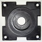
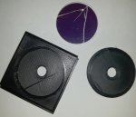
For this purpose, filter holders have been constructed, each of which can hold one or more 1-inch filters.
The holder has the dimensions of 29.9 x 29.9 x 10 mm, with a bearing seat 1 inch for the filters and a retaining ring
so that the filter remains fixed in the holder.

2.jpg

Since I use different filters optionally or at the same time,
I labeled these enclosures according to direct printing.

3.jpg

A special filter sits directly behind the IR filter on the laser input,
it is a laserline filter,which cuts the 532nm to FWHM 0,8nm.
Also this filter is from Omega optics, I ordered the one in USA,
which went then after 6 weeks AND unfortunately is broken during transport.
Unfortunately, I was not able to blame anyone for it and therefore I can sit on the harm myself.
The named seller had offered me a discount for a new purchase,unfortunately he had not done that and it was too stupid for me to ask again.
My DPSS is not very good in the relevant beam quality,
I could not afford a better laser,synonymous not a sharper filter and the spectrometer is not better anyway,
I'll deal with this here again later.... .
For this reason, I then used this broken filter and packed it well in the bracket.
So this is halfway usable even in the broken state.

4.jpg

So that these filter holders can not fall through inwardly and are secured accordingly,
I have now designed a counter-stop, which fits inwards with 0.1 mm gap between the dichro and these 30 x 30 filter holders.

5.jpg
Now the filter holders can be used, are secured inwards by the counter-holder and laterally by the respective side wall.

6.jpg

7.jpg

8.jpg

9.jpg
 
Maybe I didn't understand why the filter broken in shipping is on you as I would consider the way it was packed as being primary the cause of it breaking. I would have photographed the package if it was damaged and also if it wasn't because this would show it was poorly packaged, either way, and would bolster my case for a free replacement. I'm glad you are able to still get use out of it as you have left only the part that wasn't damage open to the laser. Good luck with the rest of this project.


Back
Top