Welcome to Laser Pointer Forums - discuss green laser pointers, blue laser pointers, and all types of lasers

LPF Donation via Stripe | LPF Donation - Other Methods

Links below open in new window

ArcticMyst Security by Avery

Possible 4 Laser Diode Project from an old Mag Light?

Joined
Jun 23, 2010
Messages
14
Points
0
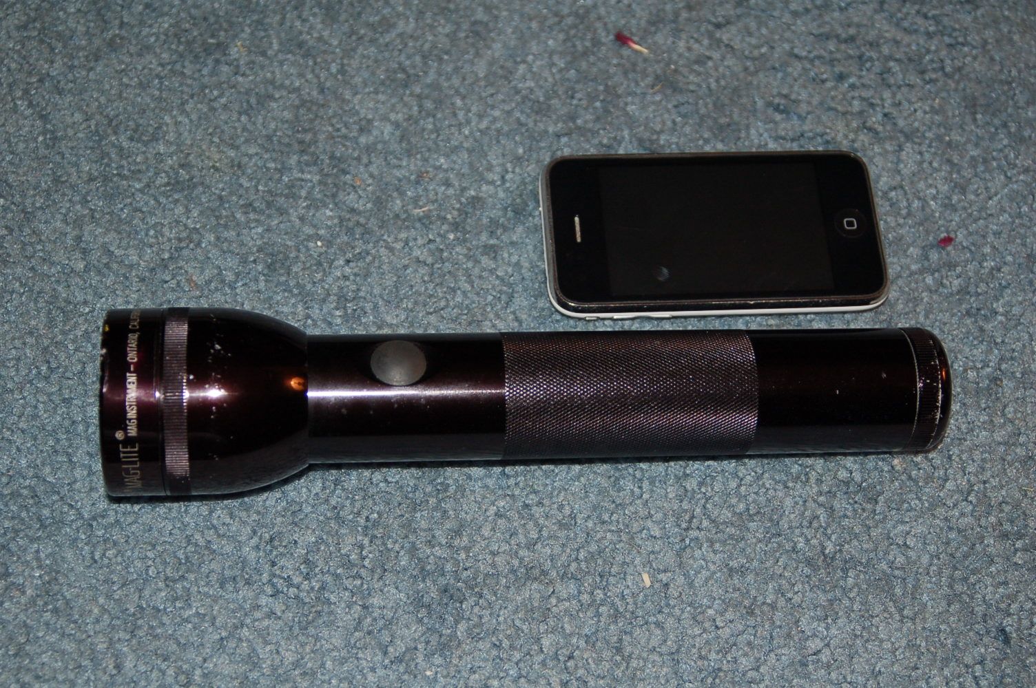
Alright guys, I have an idea for a little project. I'm thinking of turning an old Maglight below into a quad laser. In other words, I'm thinking of utilizing the large space area of the head of the light to house 4 laser diodes. The length of the shaft (including removing some plastic crap around the on/off button leave me with more than enough room to house individual drivers, switches, and a rechargeable power source... or so I theorize.

As for the diodes, I'm thinking of spending the extra cash and going for the goods including...

- 300mW 650nm Red
- 150mW 405nm Blu Ray
- 150mW 532nm Green
- 1W (probably tuned down) 445mW Blue

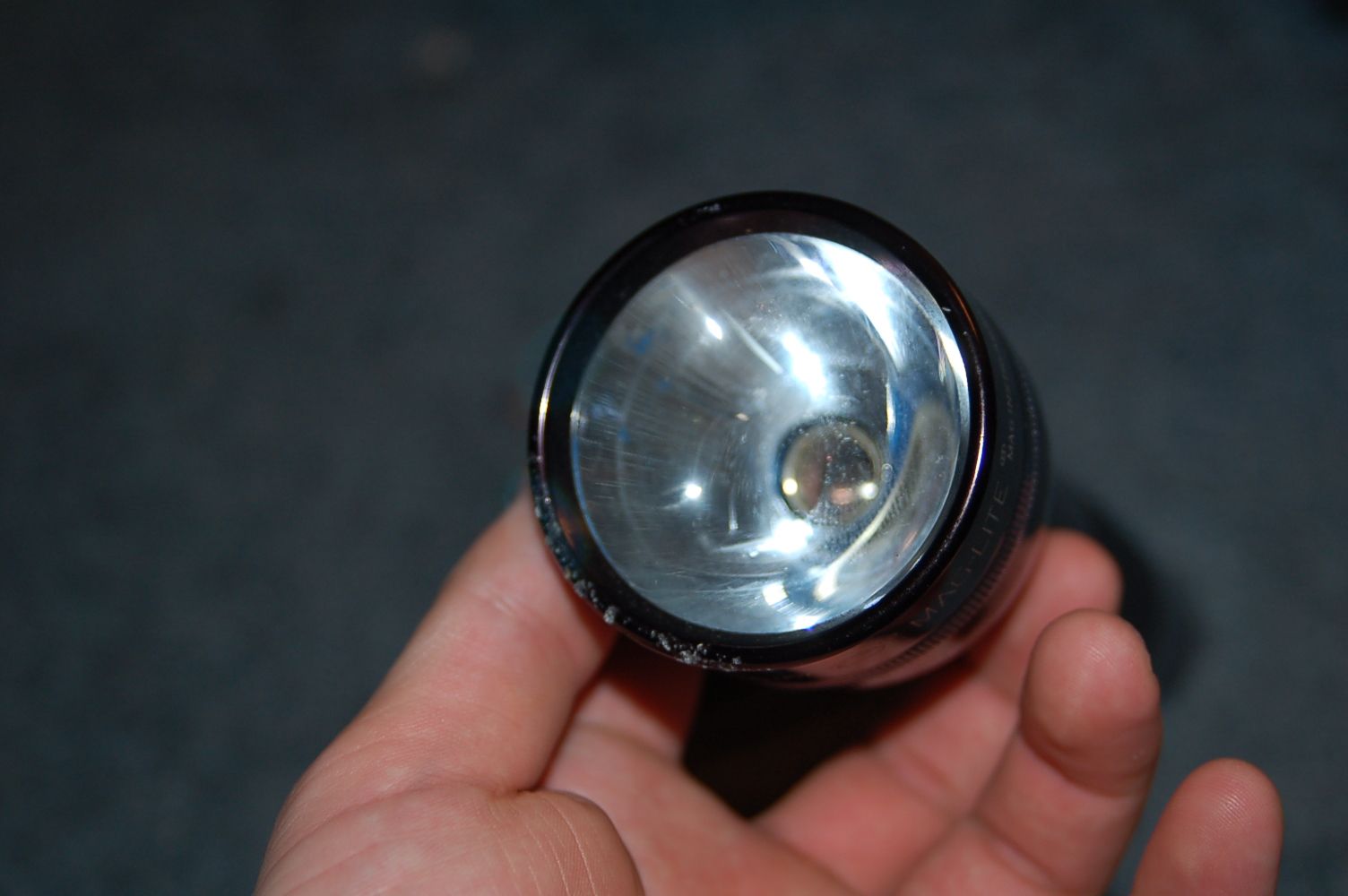
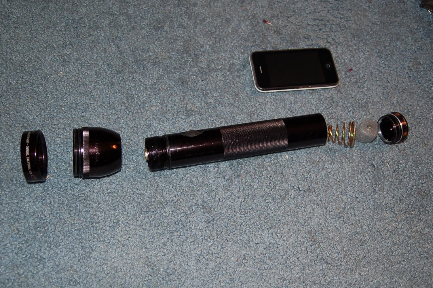
Judging by the space within the head, I can imagine fitting a CNC cut aluminum disk measuring roughly around 2.5" in diameter and .75" deep (rough estimates by sight) as a heat sink and holder for the diodes. The area where the fill plastic for the main on/off button should be around 1.75" diameter and 3" deep (not including the battery area.

What I'm working with...
DSC_0466.jpg


DSC_0467.jpg


DSC_0468.jpg


DSC_0470.jpg


MY QUESTIONS:
1. Has anyone done such a setup before?
2. Would I run into a problem running a single voltage source? I was thinking a 6V rechargeable battery I haven't yet worked that out.
3. Other than heat, are there any problems I might face having 4 diodes within the same heat sink?

Thanks guys. This would be my first build, but I'm not new to electronics.


Joined
Feb 19, 2010
Messages
443
Points
0
one problem i can immediately see, and from experience is that it will be very hard to get all beams parallel at a distance, even the slightest mm out at the torch head will make the beams become unparallel very easily. not sure if you wanted parallel beams or not?

other problems with the same heatsink is case positive/negative problems with individual diodes. 6v would do fine with enough amperage
 
Joined
Jun 23, 2010
Messages
14
Points
0
one problem i can immediately see, and from experience is that it will be very hard to get all beams parallel at a distance, even the slightest mm out at the torch head will make the beams become unparallel very easily. not sure if you wanted parallel beams or not?

other problems with the same heatsink is case positive/negative problems with individual diodes. 6v would do fine with enough amperage

I understand the first problem. I'd do my best to have them properly in sync so that I can see them all 10, 20, 30 feet away in the same pattern. I'll figure something out for that possibly including a couple different dyes.

As for the heat sink +/-, do some of these diodes have reverse polarities on the casings? Sorry for my ignorance, I've just messed with lasers in a small level.

Personally, I'd be looking to buy all the diodes with lenses from the same seller where all the casings are identical in diameter with the drivers being connected separately if that makes any sense.

For example, something like this (the diode/lens housing)...
300mW+ 650nm Red High Power burn Laser Diode Module Kit - eBay (item 280548427314 end time Aug-20-10 09:12:29 PDT)
 
Joined
Feb 19, 2010
Messages
443
Points
0
yes, i am quite sure red and green lasers have different case polarities (+ or -). violet and blue are both floating case so you may choose polarity
 
Joined
Jun 23, 2010
Messages
14
Points
0
yes, i am quite sure red and green lasers have different case polarities (+ or -). violet and blue are both floating case so you may choose polarity

Hmmm. I guess I have some homework to do on this. I will have to look into whether the casings of the diodes I'm considering also carry the polarity with them or not. I'm not planning on mounting the diodes alone into the heat sink, but rather pre-built housings, so the casing would be my concern at this point.

:undecided:
 

Toke

0
Joined
Jul 25, 2010
Messages
1,099
Points
0
There is plenty of room in that MAG.
The alignment and polarity problems could be solved by having the module holes in the heatsink big enough for some plastic foil around each module, and some toothpicks :) in the back.

That will give you a problem with heat sinking.
 
Joined
Jun 23, 2010
Messages
14
Points
0
There is plenty of room in that MAG.
The alignment and polarity problems could be solved by having the module holes in the heatsink big enough for some plastic foil around each module, and some toothpicks :) in the back.

That will give you a problem with heat sinking.

How about the heat sink being cut into a four piece pie where each section is alone divided by the others? Each would theoretically have their own heat sinks, yet fit together properly. I could make the the host/Maglight devoid of holding any current by isolating the buttons and battery. Should this work?
 
Joined
Aug 30, 2008
Messages
6,891
Points
83
Does thermal epoxy conduct electricity??? If not....read on.


Simple make everything like normal, case-negative for your 405, 650, and 445
with the positives fed into the switch.

On your 532nm, drill out the hole bigger than the actual module, Then line it, or the module with thermal epoxy and let it dry. Pretty much to give one of the two a protective layer to keep from conducting electricity.

Once this is done, you can wire the positive from the module onto the switch like the others, and put a jumper from the negative somhhwere on the host or heat sink
 

Toke

0
Joined
Jul 25, 2010
Messages
1,099
Points
0
That sounds way too complicated and error prone for me to do.
You would have to hold down a cylinder and make even cuts with a flat surface.
A hacksaw would not do that, and few powersaws could hold onto an object like that.
The width of the cut minus the padding will affect your final heat sink diameter, and you still need to wrap the whole thing to insulate it from case.

Your best bet is to get diodes with either neutral or same polarity casing.
 
Joined
Feb 19, 2010
Messages
443
Points
0
some thermal compunds do conduct electricity, such as arctic silver

@toke, using plastic foil around modules wouldnt be enough, if a diode goes out by less then a mm, out say 30ft the beam is gonna be crossed and going off in a different direction then the other three (thats if you get them to be perfectly straight)
 
Joined
Oct 24, 2009
Messages
2,555
Points
48
okay well seeing as this has worked great for me and will solve your problem very quickly
Drill the holes that are going to hold the lasers a little bit larger then wrap the laser casing in a thermal pad then put it in the host, the pad transfers heat quickly and does not conduct electricity.
This is how they mount multiple mosfets to the same heatsink.
As far as beam alignment you might have a problem comining the 405 and the 445nm they are a bit close but gl.
 
Joined
Jun 23, 2010
Messages
14
Points
0
Does thermal epoxy conduct electricity??? If not....read on.


Simple make everything like normal, case-negative for your 405, 650, and 445
with the positives fed into the switch.

On your 532nm, drill out the hole bigger than the actual module, Then line it, or the module with thermal epoxy and let it dry. Pretty much to give one of the two a protective layer to keep from conducting electricity.

Once this is done, you can wire the positive from the module onto the switch like the others, and put a jumper from the negative somhhwere on the host or heat sink

BRILLIANT!

This would simplify the making of the heat sink to fit. Personally (due to my ignorance of laser diodes), I did not know that the 532nm had reverse polarity. If this is the only issue, I think my project could be a reality.

Amazon.com: Arctic Silver Thermal Epoxy: Electronics
Arctic Silver Thermal (not retail packaged) Adhesive features: Made with 99.8% pure micronized silver. 62% to 65% silver content by weight. Superior thermal conductivity. Greater than 7.5 W/m°K Temperature range: - 40C to >150C (Bond strength is weakened at very low temperatures due to crystallization.) Negligible electrical conductivity. Arctic Silver Thermal Adhesive was formulated to conduct heat, not electricity. Even though Arctic Silver Thermal Adhesive is specifically engineered for high electrical resistance, it should be keep away from electrical traces, pins, and leads. The cured adhesive is slightly capacitive and could potentially cause problems if it bridged two close-proximity electrical paths. A set of Arctic Silver Thermal Adhesive consists of two tubes containing a total of 7 grams of adhesive (3.5 grams of Part A and 3.5 grams of Part

It sounds like I should put a decent amount of epoxy as to prevent a possible short. I don't see this being a major problem in regards to the minimal amperage any of the diodes.

Time to make this idea a reality. Now, all that I need is a good source for diode/module/driver setups for sale.

some thermal compunds do conduct electricity, such as arctic silver

@toke, using plastic foil around modules wouldnt be enough, if a diode goes out by less then a mm, out say 30ft the beam is gonna be crossed and going off in a different direction then the other three (thats if you get them to be perfectly straight)

But if an arctic silver epoxy were to be used where it's thinkness is of 2mm, would this really be a problem for the amperage provided? My other idea is using 'liquid electrical tape', but I don't know how heat properly transfers through it. I've used it on many close and delicate 12V car electronics with no problems. But like I said, I don't know how it would react to heat disbursement.

okay well seeing as this has worked great for me and will solve your problem very quickly
Drill the holes that are going to hold the lasers a little bit larger then wrap the laser casing in a thermal pad then put it in the host, the pad transfers heat quickly and does not conduct electricity.
This is how they mount multiple mosfets to the same heatsink.
As far as beam alignment you might have a problem comining the 405 and the 445nm they are a bit close but gl.

I know what you are talking about when it comes to thermal wrap, but wouldn't know the first place to look for it. I remember pulling apart an original XBOX to find a single processor about one inch by one inch connected with thermal wrap to a HUGE heat sink about 4" x 3" with baffles that were 2" high.
 
Last edited:
Joined
Aug 13, 2010
Messages
839
Points
28
Don't have access to a machine shop eh? They would be able to chuck a lathe up and mill 4 holes perfectly aligned for you. Might cost a pretty penny for the extra time but you could have the heatink in copper or aluminum, 2 holes a little larger diameter for the heat x-fer paste and milled to perfectly fit your host or even screw onto the battery tube (base)
 
Joined
Feb 19, 2010
Messages
443
Points
0
machine shop may be the way to go, they would probably be able to do the intensely precise work we are talking about here. thermal pad also sounds like a great idea
 
Joined
Jun 23, 2010
Messages
14
Points
0
Don't have access to a machine shop eh? They would be able to chuck a lathe up and mill 4 holes perfectly aligned for you. Might cost a pretty penny for the extra time but you could have the heatink in copper or aluminum, 2 holes a little larger diameter for the heat x-fer paste and milled to perfectly fit your host or even screw onto the battery tube (base)

Naw, that isn't a problem for me. I'm a car guy, so I have quite a few friends with full machine shops including lathes. I would have more of an issue just syncing everything together so there are no shorts.


Top