Welcome to Laser Pointer Forums - discuss green laser pointers, blue laser pointers, and all types of lasers

LPF Donation via Stripe | LPF Donation - Other Methods

Links below open in new window

ArcticMyst Security by Avery

OPEN Source: Tiny, high-current, boost driver (that is starting to work)

rhd

0
Joined
Dec 7, 2010
Messages
8,475
Points
0
Re: OPEN Source: Tiny, high-current, boost driver (that doesn't work yet)

Well, this is just a thought right now, but I'd put a 220K resistor in series with a 500K pot at pin 2 to ground. At the cathode of the schottkey diode I'd put two resistors and a pot in series to ground. First from the cathode would be 10K, then a 27K pot, then a 64K resistor to ground. The 10K resistor would be tied to pin 6 of the IC. You should be able to get 2.2volts to 6 volts out, at around 350mA to 900mA out. The LD would be tied to the cathode of the diode and ground. There would be a single cap to ground on the LD positive lead.

You've lost me - but that doesn't mean you're wrong!

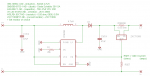
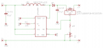
Why not draw up the schematic?


Joined
Sep 20, 2013
Messages
17,444
Points
113
Re: OPEN Source: Tiny, high-current, boost driver (that doesn't work yet)

On second thought, I see problems with this design. It was something that occurred to me when I read the spec. sheet for the IC. The feedback loop would most likely have to use the XCT1009 or similar device. That was the reason I asked for two of these. I was sure that one would be pushing my luck in trying to design this circuit. I think that the floating OC on pin 2 could be used to regulate the current as well, or could just shut the whole thing down. I'd love to have a couple of these to play with.
 

rhd

0
Joined
Dec 7, 2010
Messages
8,475
Points
0
Re: OPEN Source: Tiny, high-current, boost driver (that doesn't work yet)

That was the reason I asked for two of these. I was sure that one would be pushing my luck in trying to design this circuit.

It's always nice to have a spare!

Seriously though - my offer in the OP is still good.
 

benmwv

0
Joined
Sep 10, 2010
Messages
1,380
Points
48
Paul, I believe what you described was an adjustable voltage reg with adjustable overcurrent protection. I don't think it is really feasible to use the overcurrent protection for current regulation.

It is possible to make it adjustable without the zxct or any other current amp, but you would have to sacrifice even more efficiency than the direct resistor method and range is limited, so this is not good option. Unless somebody else can come up with something more efficient that I cant.

Im going to go ahead and try my hand at making a board, Ill post it when I get done.

Also, that last one you posted looks good rhd. I don't see any obvious mistakes to fix before you make the order.
 
Joined
Sep 20, 2013
Messages
17,444
Points
113
Ben, yeah. I came to that same conclusion as you did after looking at the circuit more closely. I agree. The bet efficiency will be achieved by using a high side current sense device like the ZXCT1009. It was just an idea I was toying with for a short while, but realized that the over current would not be a feasible way to regulate this IC. It was the floating ability of this input that gave me the idea in the first place. I could see using the low side as the feedback loop, but as you mentioned it would come at the cost of power in the form of heat.
 

rhd

0
Joined
Dec 7, 2010
Messages
8,475
Points
0
Wolfman has flagged some potential issues with the ZXCT, so even if these new revisions work, we should have some boards scoped before assuming they're safe just because they work.
 

benmwv

0
Joined
Sep 10, 2010
Messages
1,380
Points
48
Ok, here is my take on an adjustable board!

attachment.php

attachment.php


Comes in at 12mmx9mm! I changed a couple things, but it uses most of the same parts as Rhd's original. I traded out the inductor for this one ( Inductor ) which is a few mm smaller. I added a pot and dropped the set resistor to 0603, use the zxct1009 guide I posted earlier to calc their values.
The coolest change though is that I removed the shunt resistor and integrated it into the zxct1009's package layout as a pcb trace resistor:

attachment.php


By my calculations this should be right at (mabe a tad above) 0.05 ohms. Since there is a pot in this design it doesnt need to be 100% precise.

Files attached below. Be warned, I did not take the time to smash all the parts and fix all the names yet.
 

Attachments

  • NewOpenBoostForkBenV03sch.PNG
    NewOpenBoostForkBenV03sch.PNG
    9.7 KB · Views: 475
  • ZXCT1009(PCB-RESISTOR).PNG
    ZXCT1009(PCB-RESISTOR).PNG
    3.5 KB · Views: 526
  • NewOpenBoostForkBenV03.PNG
    NewOpenBoostForkBenV03.PNG
    31.4 KB · Views: 448
  • aa New Open Boost FORK-BenV03.zip
    39.7 KB · Views: 36
Last edited:

djQUAN

0
Joined
May 27, 2013
Messages
1,154
Points
63
The PCB trace resistor is a cool concept but I wouldn't recommend it. copper has a rather high temperature coefficient (that resistance changes with temp) and the heat dissipated can affect the ZXCT1009. So that would mean a driver that changes its output current when it heats up. I haven't done any calculations on how much it will change but something to consider.
 

rhd

0
Joined
Dec 7, 2010
Messages
8,475
Points
0
I notice that the new inductor has a much higher DC resistance, and also a current rating that is lower than the IC's switch current. Isn't that a concern? It's also 4.8mm tall.

How about this guy as a space saving measure that still trims a few mm off, but keeps the DCR lower, and both current rating and saturation well above switch current, and is only 3mm tall: http://www.digikey.ca/product-detail/en/MPLCG0630L4R7/399-10994-1-ND/4506446
It's also still inexpensive.
 
Last edited:
Joined
May 30, 2011
Messages
218
Points
18
Just did the calculation; from room temperature to 100 degrees F, you will see it rise from 0.05ohms to ~0.052535ohms. If using the ZXCT, you can expect it to go from say 1.53A to about 1.42A.
 
Last edited:

benmwv

0
Joined
Sep 10, 2010
Messages
1,380
Points
48
Rhd, that inductor i found is rated for 5A, isn't that plenty? And yeah it is fairly tall. I was thinking of trying a 3.3uh on it, that way it would be shorter. From my experience a 3.3 and even lower usually works just fine when the data sheet suggests 4.7. I'll order that one you suggested and a few others to see what works best. I'm just not sure if it will fit in the pad layout I used. I was trying to make this one really compact.

I'm not really worried about the pcb trace resistance rising. If it does a small amount I don't really care, as a driver board this tiny I will only use handhelds so it will only be powered on for short periods of time.

Anyways, the only way to really know is to test it which I will be doing as soon as I get my boards.
 

rhd

0
Joined
Dec 7, 2010
Messages
8,475
Points
0
Rhd, that inductor i found is rated for 5A, isn't that plenty? And yeah it is fairly tall. I was thinking of trying a 3.3uh on it, that way it would be shorter. From my experience a 3.3 and even lower usually works just fine when the data sheet suggests 4.7. I'll order that one you suggested and a few others to see what works best. I'm just not sure if it will fit in the pad layout I used. I was trying to make this one really compact.

I'm not really worried about the pcb trace resistance rising. If it does a small amount I don't really care, as a driver board this tiny I will only use handhelds so it will only be powered on for short periods of time.

Anyways, the only way to really know is to test it which I will be doing as soon as I get my boards.

You might have linked the wrong one, because it says:
Current Rating 3A

Also, I checked out the zip, and I think you zipped the wrong files. You included a .s#1 instead of the .brd

37.77 degrees Celsius for those of us who use metric units :p

I was wondering what that meant in real units ;)

To be courteous to our American friends, we should probably restate the dimensions of Ben's 12x8mm board in imperial measurements.

The board is roughly 4 Popyseeds by 1 and a half Barleycorns. :wave:
 
Last edited:

benmwv

0
Joined
Sep 10, 2010
Messages
1,380
Points
48
Oh wow looks like I was slipping up haha. I'll fix the zip and figure out the inductor situation when I get back to my pc later today.

ARG, haven't heard from you in a while! How did finals treat you? :eg:
What's your opinion on this pcb trace as a shunt?

All you people from the rest of the world think you are so much better than us with your silly "SI" units and powers of 10. :gun:
 

rhd

0
Joined
Dec 7, 2010
Messages
8,475
Points
0
I'll fix the zip and figure out the inductor situation when I get back to my pc later today.

(...)

All you people from the rest of the world think you are so much better than us with your silly "SI" units and powers of 10. :gun:

No rush Ben. We're patient. We don't mind waiting a few blinks of a possum's knuckle, as long as it doesn't take you half a fortnight and a moon cycle. :p

Here's a V08. It upgrades to the Kemet inductor I linked previously (digikey part number in the schematic). It also kicks the size of the board down to 10x10 mm. A nice clean square centimeter.

attachment.php


attachment.php
 

Attachments

  • New Open Boost V08.zip
    34.3 KB · Views: 44
  • Schem V08.png
    Schem V08.png
    8.8 KB · Views: 455
  • Board V08.png
    Board V08.png
    41.3 KB · Views: 340

benmwv

0
Joined
Sep 10, 2010
Messages
1,380
Points
48
Square centimeter board, I like it.

The inductor I posted is rated for saturation current (DC) 5.5A
The other current value is (in my understanding, might not be exactly right) the max rms value of the wave going into the inductor to run continuously without overheating. Ive always gone by just the saturation current and the dc resistance to chose the right inductor. Since the max possible DC current is 4.5A it should stay well within its ratings for saturation.

Also, I think im going to try this one: Inductor
I have generally always used the ferrite drum core inductors but I have seen some people here using powdered iron inductors on boost and buck drives. I tried one out on another drive once and it worked just fine. The powdered iron inductors are much smaller than the ferrite drum cores. Im no expert on different types of inductors, but i believe ferrite are much better for high frequency? Im sure there is much more to it than that. The frequency range we use in dc-dc converters (usually 100khz to 1Mhz) is suitable to either type i think.

Hopefully somebody who is well versed on inductor cores can clear this up because i'm pretty clueless here.

Here is the fixed zip file for the board I posted earlier.
 

Attachments

  • aa New Open Boost FORK-BenV03.zip
    39.7 KB · Views: 27


Top