Welcome to Laser Pointer Forums - discuss green laser pointers, blue laser pointers, and all types of lasers

Buy Site Supporter Role (remove some ads) | LPF Donations

Links below open in new window

FrozenGate by Avery

OPEN SOURCE: "CC-Boost" - 2.4 Amp boost driver - RC1

Re: OPEN SOURCE: New Boost Drive, 2.4A capable from one cell, tested and working

rhd, after the last couple of posts on this I find of thought this was where you were going. I see no problem with it and the ideas are sound, but the test of this new layout will tell all.


Re: OPEN SOURCE: New Boost Drive, 2.4A capable from one cell, tested and working

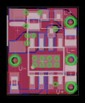
See latest Beta V13 below. I like the improvements in layout and design with this board. It takes us to an 8 uH inductor, and places 3x 22uF caps before the ZXCT, as well as one after (to deal with the ZXCT startup disturbances). The GND to output caps has been kept short, and the FB trace is so short it's almost not a trace anymore. Even with these changes, the size has only increased to 12 x 9.5.

If this board scopes well, we wouldn't have much trouble trimming off 0.5mm of width to get the size identical to a FlexDrive (12x9)

attachment.php


attachment.php
 

Attachments

Re: OPEN SOURCE: New Boost Drive, 2.4A capable from one cell, tested and working

Looks like a great board to me man!

You've really got the layout optimized in this one. All the important traces are super short.

Only thing I might change is to pop in some more via up in the top left corner at the diode. What you have is probably good enough, but at currents this high I think it's better to be safe than sorry. The most critical part is making sure the caps have a very low resistance path since the ripple currents going in to them can be much higher than the output current.

Will do.

Do you think it would be worth taking this board 4-layer, and adding an internal GND later, and an internal _________ layer?
 
Re: OPEN SOURCE: New Boost Drive, 2.4A capable from one cell, tested and working

Well it definitely wouldn't hurt to do but I don't know if it would be worth it.

I know these tiny boards are cheap, but it is double the price to get 4 layer. Is there enough benefit to justify that?

Also, seems like only the gnd would benefit from having more layers, so just make them both gnd? That would definitely help with heat spreading. Also you could run the trace going from the zxct to the set resistor in the upper middle layer so that there is a full layer of gnd between it and the inductor for shielding.

I'd say just fork it so everyone can choose if they want to use the 4 or 2 layer version.
 
Re: OPEN SOURCE: New Boost Drive, 2.4A capable from one cell, tested and working

Where are we on this? Do we have a reliable version yet? Scope is a bit dirty still, but may be ok for less sensitive diodes?

Let me know, great work guys!

Matt
 
Re: OPEN SOURCE: New Boost Drive, 2.4A capable from one cell, tested and working

It occurred to me that throwing caps at the problem isn't the solution. I crunched my brain on some numbers to see how we're doing with Inductor selection.

Ripple = (Vin * ( (1 - (Vin / Vout)) / Freq) * 1000) / L
or
L = (Vin * ( (1 - (Vin / Vout)) / Freq) * 1000) / DesiredRipple

So, based on the 6.8 uH inductor we've been using, and assuming, for simplicity, 4.5V output voltage to the diode and a li-ion's 3.6V nominal voltage as the input, here's what ripple we should have seen:

Ripple = (3.6 * ( (1 - (3.6 / 4.5)) / 500) * 1000) / 6.8
Ripple = 210 mA

That's a lot of ripple, and explains what we're seeing on ARGs test results. If we want to target 50mA of ripple, here's where we need to be:

L = (3.6 * ( ( 1 - (3.6 / 4.5)) / 500) * 1000) / 0.05
L = 14.4 uH

The best candidate inductor I could find that (A) keeps price low, (B) keeps size small, (C) can handle the current with a safe margin, and (D) hits the new inductance target, is this:

ASPI-0630LR-150M-T15CT-ND
Abracon Corporation - INDUCTOR POWER 15.0UH 0630 SMD
 
Last edited:
Re: OPEN SOURCE: New Boost Drive, 2.4A capable from one cell, tested and working

You wizardry is beyond my simple ("simple") electrical knowledge, so here, have some rep.
You absolutely sure this would solve the problem? If so, who has a rework station and wants to give it a shot?
 
Re: OPEN SOURCE: New Boost Drive, 2.4A capable from one cell, tested and working

You absolutely sure this would solve the problem? If so, who has a rework station and wants to give it a shot?

Nope. Won't be sure until it's scoped ;)

But I think the new inductor, plus my previous board revisions, could be a win.

ARG: would you be up for scoping another driver? If not, we can try and spread around the scoping duties.
 
Re: OPEN SOURCE: New Boost Drive, 2.4A capable from one cell, tested and working

I'm up for it. :)
Not sure of the time line for this, but I will be away next week.
 
Re: OPEN SOURCE: New Boost Drive, 2.4A capable from one cell, tested and working

I'm up for it. :)
Not sure of the time line for this, but I will be away next week.

No rush. The V13 boards have shipped from Oshpark, but they're not here yet. I need to place a digikey order for parts anyway.
 
Re: OPEN SOURCE: New Boost Drive, 2.4A capable from one cell, tested and working

I see the inductor increase keeping the ripple out of the supply, but how is it going to affect the output? I must be missing something here.
 
Re: OPEN SOURCE: New Boost Drive, 2.4A capable from one cell, tested and working

I see the inductor increase keeping the ripple out of the supply, but how is it going to affect the output? I must be missing something here.

I'm very confused by your question ;)

What do you mean when you say that the inductor will keep the ripple out of the supply? That doesn't make sense to me. The supply isn't the problem here anyway, it's not the source of the ripple.
 
Re: OPEN SOURCE: New Boost Drive, 2.4A capable from one cell, tested and working

Maybe I'm wrong here, but the output at pin 8 of the IC is the 500KHz with an adjustable duty cycle of up to 90%. The shcottkey diode is rectifying the FET output at pin 8 and filtered by the caps at the cathode of D1. The choke is between the supply voltage and the output of the internal FET and is there to keep the current of the PWM output at pin 8 from getting back into the source voltage, or rather the enable and the Vcc pins of the IC. I guess the thing to do is to go to the spec sheet of the IC to see exactly how this works. But, if I'm not wrong, the output noise won't be greatly affected by increasing the value of the choke.
 
Last edited:
Re: OPEN SOURCE: New Boost Drive, 2.4A capable from one cell, tested and working

The inductor provides the reactance to limit current. It is the single most important component in this type
of switching regulator. Everything else can be substituted with different things, but there MUST be a coil.
It's not just there to provide filtering of the input power or perform some secondary role. It is at the very
heart of the circuit.
 
Re: OPEN SOURCE: New Boost Drive, 2.4A capable from one cell, tested and working

Yeah, I get that, but increasing the inductive reactance of this part of the circuit isn't going to limit your noise at the output, from what I can see. All boost PWM circuits like this one have an inductor to limit the current of the output, but as your noise is part and parcel of the FET's output and this is a function of the output from the feedback circuit and the current sensing device I don't get the increase as reducing the noise by its increase.


Back
Top