Hello,
Are lasers more efficient when pulsed? 50W 100%duty vs 100W 50% duty
Do you plan to use the TEC? I wonder how much size, power, and output heat will need to be sufficient for the 200W at Max power.
I am no expert, but I can make an educated guess:
I believe its inefficient to pulse the diodes 50/50% vs driving at 1/2 current because:
The formula for power is: P= I² x R
So for example the connections at the bond wires and external wiring = 0.2R (its just an example)
If you drive the array with 1A you will get 1² x 0.2R =0.2W
If you drive the array with 2A you will get 2² x 0.2 = 0.8W now divide that by 2 for half the time active = 0.4W
You can easily see that increased current will get the efficiency down fast.
Somebody may say: "but what about the temperature".
This is a rabbit hole, please be careful
")
If the temperature inside the laser diode crystal rises the efficiency drops significantly.
Theory: if you drive the diode 1/2 of the time the crystal has time to "cool" and runs cooler so more efficiency.
My guess:
The laser crystal is really really small inside the diode. So even if it has time to cool between pulses, when the pulse starts the crystal will get hot really fast because the mass of the crystal isn't big so it can not absorb a significant amount of energy before heating up.
Combined with the fact that the efficiency drops with increased current -> look at the chart inside the data sheet for the PL_TB450B diode.
Link from DTR: docs.google.com/file/d/0B_6-KC5wFXIJTXBfTmJjY1lMamM/edit
Also think about the stress that the crystal experiences:
If you look closely at the data sheet mentions 15k/w thermal resistance between case and crystal.
This means the crystal will get 15K warmer if you pass 1W through it.
Quick calculation to calculate the temperature if it runs full power:
Let us calculate with the values that dtr shows, 1.5A to not "overdrive" it, lets assume its cooled with a tec to 20°C
DTRs pictures show it needs 5V for 1.5A so thermal power would be: P=(I x V)-Po
Po is optical power, this needs to be subtracted to get thermal power inside the crystal.
(1.5A x 5V) - 1.8W = 5.7W
To calculate the temperature we can do:
(5.7W x 15K/W) + 20°C = 105,5°C for the crystal.
To get everything together the same calculation for 1/2 power (values also from DTRs pictures):
Crystal thermal power:
(0.8A x 4.6V) - 0.9W = 2.8W (you can even see that the efficiency is higher steady state without pulsing)
Crystal temperature:
(2.8W x 15K/W) + 20°C = 62°C
So if you pulse the diode the crystal will experience rapid heating from 20°C to 105°C, but in reality its worse because the thermal resistance from case to mount is ignored.
If you drive the diode 1/2 current the temperature will drop, this is good because the diode will be more efficient.
Combine the two and you get reduced efficiency if you pulse the diodes.
More current equals to more resistive losses inside the diode, wiring and driver
More current also equals to higher temperatures for the crystal equals to higher losses and more stress: shorter lifetime.
Again, I am no expert, but for me at least it makes sense to drive the diodes with reduced current if you want less power.
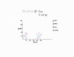
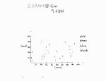
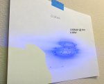
I would also like to see a picture of the multi beam profile.
Could you please make a picture of the spot from this array on the wall through OD6 googles at let us say 1 and 5m distance passing low current through each row. 0.3-0.5A would be enough I think. Like I did in my studies of NUBM08/44 arrays earlier here on LPF.
I will make a picture for all of you, but I can currently not leave my home because of the virus, if I get to my workshop I will make pictures.
Would be nice to know if its luck or if all the modules are the same, I only have one so I cannot do a comparison.
Light superglue /Likevvii said:
I currently don't use a TEC, it can be done but I don't know if it is really the smartest thing to do.
We need something that's capable of pumping more than 200W so my idea would be to use a TEC1-24116.
It could pump hold the module at 20°C if we can get the hot side to around 50°C but it will need 420W to accomplish this.
This means we go from 300W overall power to 720W, this will drop the efficiency of the overall design to very low values without adding much benefit.
If we can thrust the datasheets for the NUBM31 module, the module has no problems with running at 70°C case temperature.
So if we use a TEC then we need to get a much bigger heatsink.
Quick calculation:
With TEC 720W @ 50°C with 35°C ambient
50°C-35°C = 15k headroom for the heatsink
15K / 720W = 0,02K/W Heatsink
Without TEC 200W @ 70°C with 35°C ambient
70°C - 35°C = 35K headroom
35k / 200W = 0.175 K/W Heatsink
As everybody can see the heatsink needs to be roughly 10 times as huge if we use a TEC.
Water-cooling may be needed for a TEC.
Without tec it doesn't look bad, 0.175K/W is not such a big heatsink. Spread of the heat across the heatsink should also be ok, maybe we need heat pipes.
I did mount it on a heatsink that's forced air cooled and has around 0.15k/W but I didn't power the module long enough to see significant temperature increase.
If you have a remote phosphor application it might be needed because the wavelength shift that occurs if the module reaches higher temperatures. But I don't have knowledge at this topic.
Sorry for my long post, please respect that I am not a native englisch speaker, but I think I did a good job of explaining.
Have a nice evening.