LPF Donation via Stripe | LPF Donation - Other Methods
Links below open in new window
ArcticMyst Security by Avery


You are using an out of date browser. It may not display this or other websites correctly.
You should upgrade or use an alternative browser.
You should upgrade or use an alternative browser.
Noob Here
- Thread starter CVlaxstar
- Start date


daguin
0
- Joined
- Mar 29, 2008
- Messages
- 15,989
- Points
- 113
CVlaxstar said:Alright, so i got this on ebay and would like to know what to do with it. I looked through some of the tutorials, but didn't see any that helped.
can't post links yet so search this
270339463127
Here ya go
http://cgi.ebay.com/ws/eBayISAPI.dll?ViewItem&item=270339463127&_rdc=1
You can build it and have a nice little laser. You won't get 150mW out of 110mA with it, but you will be able to burn stuff with it. You will probably end up with more like 95mW.
You could have gotten it here, with the driver already built and attached, for about the same price, but it should be a nice little laser when you're done
Peace,
dave
rog8811
0
- Joined
- Jul 24, 2007
- Messages
- 2,749
- Points
- 0
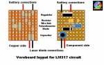
You have some extra bits with that kit, this is the layout most people use here. resistor shown is a 10ohm which will allow a max current of 125mv you could do with another ohm to get it around 110ma. Can you list the resistor values so that we can work out your options.
Regards rog8811
Regards rog8811
Attachments
- Joined
- Feb 22, 2008
- Messages
- 3,182
- Points
- 48
looks like a potentiometer whow did i spell that right
crap oh yea back to bed lol
crap oh yea back to bed lol
rog8811
0
- Joined
- Jul 24, 2007
- Messages
- 2,749
- Points
- 0
The grey line between the resistor and the pot is a link to join 2 tracks, it just makes the layout easier.
Regards rog8811
[edit]As you are the second one to ask that question... I have annotated the drawing") [/edit]
[/edit]
Regards rog8811
[edit]As you are the second one to ask that question... I have annotated the drawing
[/edit]rog8811
0
- Joined
- Jul 24, 2007
- Messages
- 2,749
- Points
- 0
I have not managed to access your photobucket account so cannot see your pictures.
If I understand you correctly, you push the components through the holes from the side without the copper stripes, solder the leads (making sure you only bridge across to the next track where shown in the drawing) You then snip off the rest of the wire that sticks out from the solder.
Regards rog8811
daguin
0
- Joined
- Mar 29, 2008
- Messages
- 15,989
- Points
- 113
rog8811 said:I have not managed to access your photobucket account so cannot see your pictures.
If I understand you correctly, you push the components through the holes from the side without the copper stripes, solder the leads (making sure you only bridge across to the next track where shown in the drawing) You then snip off the rest of the wire that sticks out from the solder.
Regards rog8811
http://photobucket.com/albums/k34/CVlaxstar/IMG_1058.jpg
Peace,
dave
rog8811
0
- Joined
- Jul 24, 2007
- Messages
- 2,749
- Points
- 0
Just don't leave a blank line of holes down each side.I have a 14 * 7 vero piece any chance i could fit it on this?
Nope, says photo not correctly linked when I try.
Regards rog8811
daguin
0
- Joined
- Mar 29, 2008
- Messages
- 15,989
- Points
- 113
rog8811 said:Nope, says photo not correctly linked when I try.
Regards rog8811
One more try. It's not that helpful a photo anyway
http://i84.photobucket.com/albums/k34/CVlaxstar/IMG_1058.jpg
Peace,
dave
- Joined
- Oct 26, 2007
- Messages
- 5,438
- Points
- 83
daguin said:One more try. It's not that helpful a photo anyway
http://i84.photobucket.com/albums/k34/CVlaxstar/IMG_1058.jpg
That is a very lovely empty cola can, yes indeed. Too bad it's obscured by that blurry thing in the front.
