Welcome to Laser Pointer Forums - discuss green laser pointers, blue laser pointers, and all types of lasers

Buy Site Supporter Role (remove some ads) | LPF Donations

Links below open in new window

FrozenGate by Avery

Nixie Tubes! Awesome Deal!

RayJay

0
Joined
May 2, 2014
Messages
344
Points
0
Hey everyone,

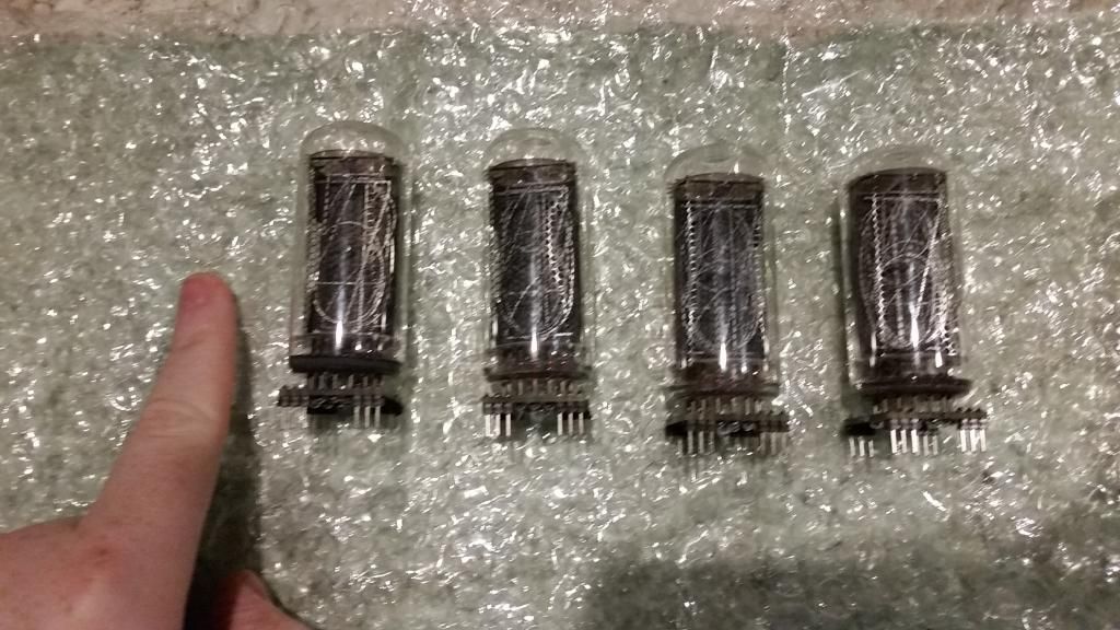
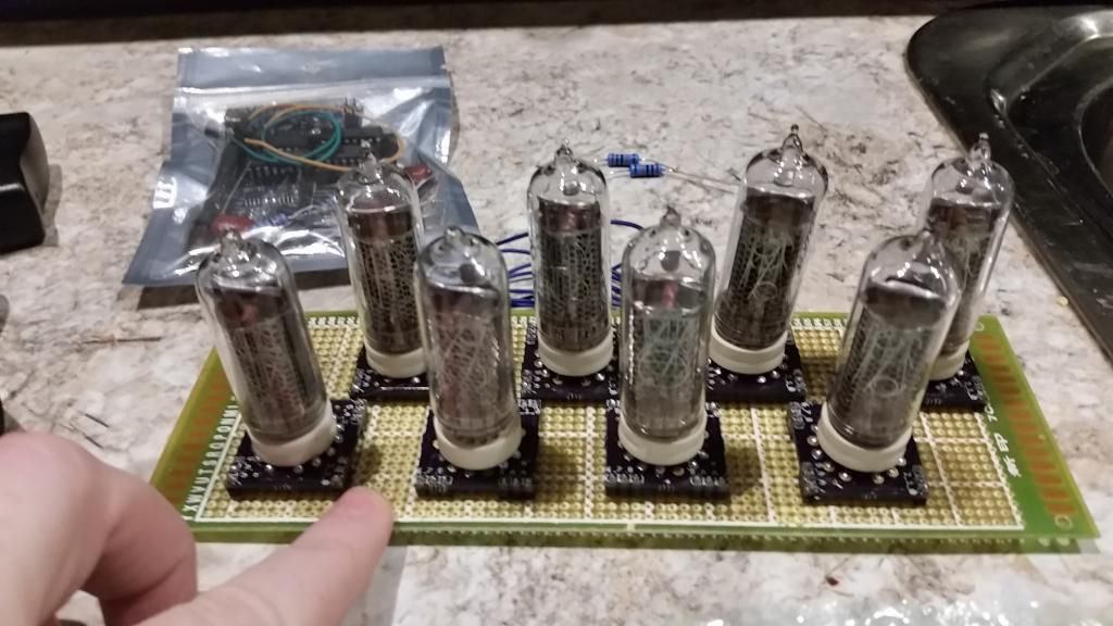
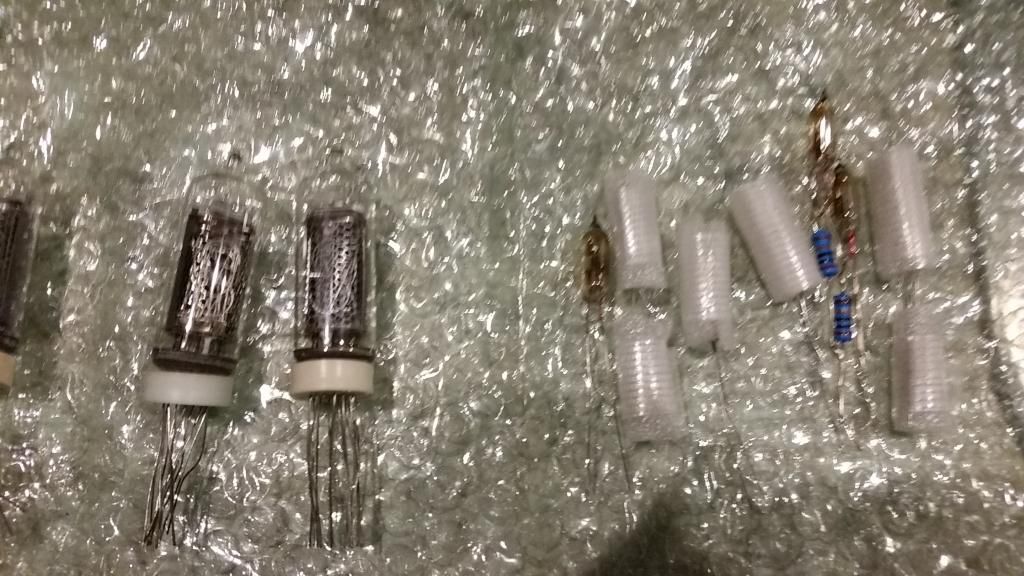
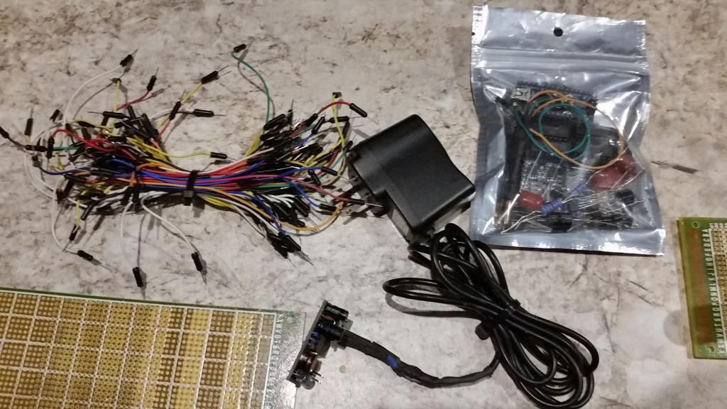
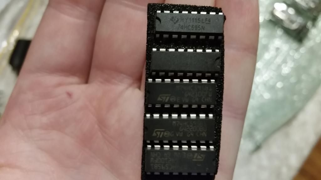
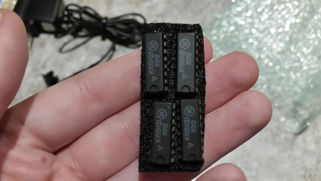
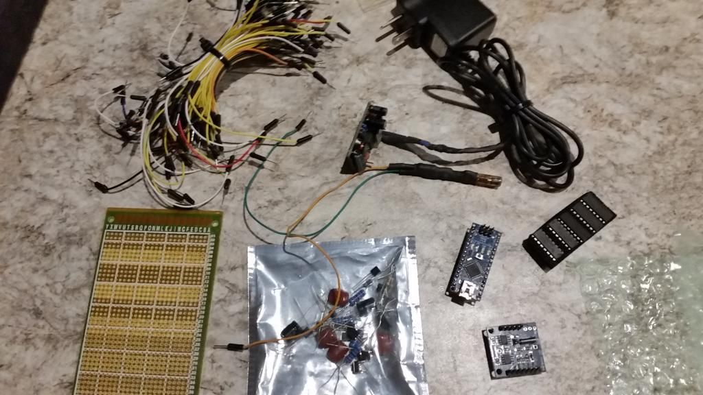
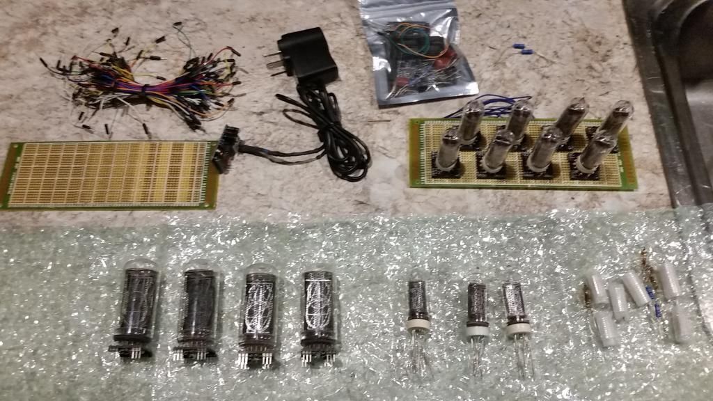
I got in a package today!

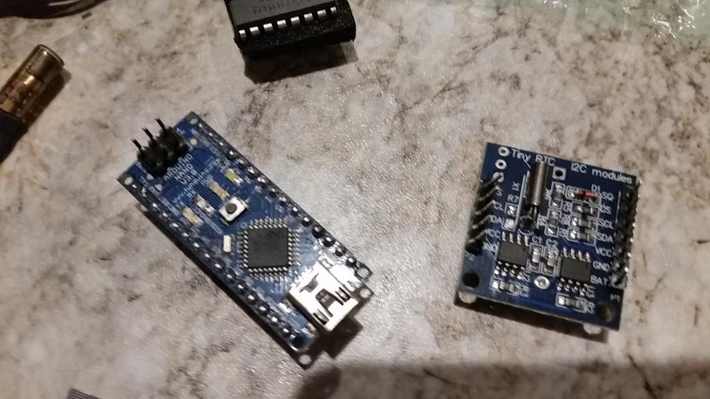
I'll let the photo's do the talking..
20140715_140134_zps215eb44d.jpg


20140715_140143_zps7f5e009a.jpg


20140715_140154_zps5335066e.jpg


20140715_140158_zps6b2d3e8d.jpg


20140715_140207_zps57fcfe8b.jpg


20140715_140512_zpsf77ec4c1.jpg


20140715_140452_zps63da9eb1.jpg


20140715_140427_zps5c25d10b.jpg


20140715_140440_zps85228d69.jpg


Things included are..
4 x IN-18
2 x IN-14
4 x IN-19A
5 x IN-19B
9 x colon markers
1 x Arduino Nano V3.0
1 x Tiny RTC 12C Module
2 x Proto Boards

And a TON of wires, diodes, etc that I have no idea what they are/do?!
I also think there is some type of sensor (temp maybe?) in the middle of the second last photo?

So, I have been told that I have "most of the parts" to make a clock..
I know I have more than enough tubes!! (although I was expecting 6 IN-18's instead of 4..but who's complaining!)

The thing is... I have no idea what I am looking at here? And have NO idea what to do?? Any tips? Fiddy? I know you have made a few..

Are there any schematic's or tutorials online? I was just going to buy a kit from PVElectronics but I thought if I already have everything here i'd try myself first..

Thanks guys!
 
Last edited:


What's your level of electronics experience? Will help a lot to know when we're giving help.
 
What's your level of electronics experience? Will help a lot to know when we're giving help.

I have a bit.. I can solder well! :yh: I just don't know anything about arduino's? I have been doing a bit of reading in the last few hours.. Seems reasonably easy. I just can't find any schematics or even full parts lists.
 
Wow, lol, I'm really new to soldering but can't wait to start building something. I have to order a ton of electronics on eBay though... I just got my soldering iron last week.
 
Arduino code (C++) isn't hard to learn the basics of. Arduino main site has an AWESOME amount of tutorial basics and info to learn from. Adafruit company also has a ton of great tutorial stuff as well. If you can determine what a chunk of code does via its example in the tutorials and then mentally label that chunk and repurpose it for your own project you'll do just fine. Get to know the physical limits of the arduino; it can't supply much current, it can't switch very fast, and it has no protection for if you accidentally plug something in the wrong spot.

You'll need to understand some basics electronics principles:
-conventional current flow mechanics and directionality (current flows reverse the direction that electrons flow).
-Ohm's law and it's three permutations: V = IR, I = V/R, R = V/I
-ohmic losses law: P= I ^2 * R
-a basic understanding of simple discrete electronic devices; how they function (in terms of how they are hooked up, and what voltage/current at what points makes them do that. You don't need to know the physics behind them at all) and what their ratings are and what those ratings mean. Know your: capacitors, resistor, NPN and N channel Transistor/MOSFET, diodes, transformers, inductors, and input/output devices (LEDs, sensors, speakers, buzzers, microphones, etc).

With the above under your belt you can build a tremendous array of cool things. I don't mean building from someone else's schematic, either, but create your own too!

For a nixie clock you need a logic controller (like the arduino), configured (in the case of the arduino via code) to keep human readable time and output the time signal in such a way that four seven segment displays can run off of it. Once you have that it is simply a matter of using hooking the 7segments x 4 signal output from the controller to a nixie display. This means that you need to switch a higher voltage that can run the nixie segments with the smaller voltage and low current that the controller can provide. A job for transistors!

Now, how to specifically use an arduino for this I don't know off the top of my head. I tend to think like an analog engineer, and the modern digital stuff eludes me more often than not. If I were doing it I would have 28 I/O lines each driving a single segment of the display. I'd write subroutines; one for each number, and then call the subroutines in the right order and to the right 7seg-display as needed by the current time. I'm sure there are specialty commonplace 7seg-display driving ICs and shields and modules now but I don't know them. I think you can even use a special programming topology that quickly lights one display at a time and rotates them relying on persistance of vision so you only need 7 I/O lines. Still, I do things like an EE in the 1970s.
 
Thanks Sigthur!

I already have a pretty good grasp on the basic electronic principles due to making my own drivers etc.. You have to know V=IR to set the current on a driver.. I have done many electronic kits (actually working on a theremin right now!) and have a good grasp on electronics.. If I have Instructions!

I have been thinking about just buying a kit from pvelectronics and putting it together from scratch..
And then just sell the rest of the stuff I got in this package that I don't need. (see anything you're interested in? :whistle:)


Arduino code (C++) isn't hard to learn the basics of. Arduino main site has an AWESOME amount of tutorial basics and info to learn from. Adafruit company also has a ton of great tutorial stuff as well. If you can determine what a chunk of code does via its example in the tutorials and then mentally label that chunk and repurpose it for your own project you'll do just fine. Get to know the physical limits of the arduino; it can't supply much current, it can't switch very fast, and it has no protection for if you accidentally plug something in the wrong spot.

You'll need to understand some basics electronics principles:
-conventional current flow mechanics and directionality (current flows reverse the direction that electrons flow).
-Ohm's law and it's three permutations: V = IR, I = V/R, R = V/I
-ohmic losses law: P= I ^2 * R
-a basic understanding of simple discrete electronic devices; how they function (in terms of how they are hooked up, and what voltage/current at what points makes them do that. You don't need to know the physics behind them at all) and what their ratings are and what those ratings mean. Know your: capacitors, resistor, NPN and N channel Transistor/MOSFET, diodes, transformers, inductors, and input/output devices (LEDs, sensors, speakers, buzzers, microphones, etc).

With the above under your belt you can build a tremendous array of cool things. I don't mean building from someone else's schematic, either, but create your own too!

For a nixie clock you need a logic controller (like the arduino), configured (in the case of the arduino via code) to keep human readable time and output the time signal in such a way that four seven segment displays can run off of it. Once you have that it is simply a matter of using hooking the 7segments x 4 signal output from the controller to a nixie display. This means that you need to switch a higher voltage that can run the nixie segments with the smaller voltage and low current that the controller can provide. A job for transistors!

Now, how to specifically use an arduino for this I don't know off the top of my head. I tend to think like an analog engineer, and the modern digital stuff eludes me more often than not. If I were doing it I would have 28 I/O lines each driving a single segment of the display. I'd write subroutines; one for each number, and then call the subroutines in the right order and to the right 7seg-display as needed by the current time. I'm sure there are specialty commonplace 7seg-display driving ICs and shields and modules now but I don't know them. I think you can even use a special programming topology that quickly lights one display at a time and rotates them relying on persistance of vision so you only need 7 I/O lines. Still, I do things like an EE in the 1970s.
 
The Chips you have , k155XXX which is the same as the 74141 or 7441 drivers are high voltage BCD to 7 Segment drivers that are able to drive the nixie tubes ,

here is info and data on them - http://www.tube-tester.com/sites/nixie/74141-NDT/74141-NDT.htm

There are a few ways to make the BCD part using 2 dual BCD and a Quad AND gate IC with a 4060 and 32.somethingKhz crystal to produce the 1Hz clock ( the logic side is all 5 volts )

Im using the same method above to drive a led clock I made that will be converted to VFD @ 17 Volts using HEF4543 BCD-7 Seg drivers ( just need to make the 4060 1Hz generator )

This is is abit simpler over the arduino way , but you have no real control over the displays ( individually addressable ) and it will only display time .

Or you could use the arduino to generate the BCD and that would require 16 pins with 4 for each IC ( again all 5 Volts logic )

BCD is pretty simple each line ABCD represents a number 1248 .

With this combination you can make any number , so for the 7 segment driver to display 5 , line A and C need to be HIGH with D and B LOW .
 
Last edited:


Back
Top