Welcome to Laser Pointer Forums - discuss green laser pointers, blue laser pointers, and all types of lasers

Buy Site Supporter Role (remove some ads) | LPF Donations

Links below open in new window

FrozenGate by Avery

Nichia NUBM34T 115W 455nm

tedcs

0
Joined
Jul 27, 2012
Messages
48
Points
18
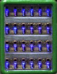
I received a NUBM34 from "Newgazer "on eBay. It was ordered April 29, delivered May 7, by FEDEX, no problem. The 24 diodes are mounted on the base plate, each has a bypass zener diode. A mirror, at 45 degrees, reflects the output normal to the face of the device.

IMG_0542 50.jpg IMG_0583 c.jpg IMG_0581 c 2.jpgIMG_0600 33.jpgIMG_0591.JPG
I have limited the current to way below the lasing threshold so far. (220 - 420 mA ?)
I'm new at this, and don't wish to vaporize my eyeballs, camera, the device, or burn the house down.
17 v will light a row of diodes. On 18 v, it draws 1 mA. Some preparation is necessary before I can crank it up.
(Yes, I have good quality laser glasses, per StyroPyro )
 
Last edited:


Very interesting, I had expected the divergence of each beam would be worse than what we have seen.......I would not be suprised if there is some small amount of beam shaping going on and I am impressed at the factory alignment of these so far.
 
Very interesting, I had expected the divergence of each beam would be worse than what we have seen.......I would not be suprised if there is some small amount of beam shaping going on and I am impressed at the factory alignment of these so far.

Yes interesting--they seem to be designed for long life and without consideration of being used for purposes other than in the intended projectors they are intended for.
 
Last edited:
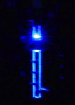
A stainless steel bar was placed on top of the NUBM34, without lenses. The weight of the bar presses the device against a large aluminum block which serves as the heat sink. One row of diodes is aligned with one edge of the stainless bar such that the laser diode emission is visible on the side of the bar. (The stainless bar is 3 inches tall, a lead ingot rests on top.)

IMG_0638sc.jpg IMG_0637 33.jpg (Lasing threshold is about .420 Amps @ 20.5V, for each six diode row )
 
Last edited:
Very interesting, I had expected the divergence of each beam would be worse than what we have seen....

I thought it could be interesting to see what the beam pattern looked like at the surface of the diode window, with the gang-collimator lenses removed. A piece of thermal paper was placed on the device, and one row of diodes were supplied with 1 Amp for 3 seconds. An image was created on the thermal paper. With lens array attached, it will certainly be quite different.

(Image overlayed)
Nichia NUBM34 burn.jpg( <–––––– See lowest row beam pattern print )

(Image of array from flat bed scanner - terrible depth of field)
 
Last edited:
Yep, they do appear to suffer from the same aggressive fast axis divergence as the other single nubm's and have the same ribbon/rectangle shape.....of course the narrow part ( left-right ) will diverge much faster than the tall part and this is a limiting factor.....I suspect after looking at Drakes video that the mirrors are slightly tilted inward to help the beams converge in the near field, this would be to aid in pumping the phosphor in projectors after their unit specific lenses.
 
Yep, they do appear to suffer ...
A thermal print of the NUBM34 was made with the lenses reattached. Three diode rows were powered. That the prints are rather distorted suggests that the lens alignment is slightly off, I suppose.
IMG_0639c.jpg
I'm considering optical options, while attempting to decide on the most entertaining purpose for the device.
 
I would rather have seen some 10w diodes than this cluster deal, that gang lens in a real abortion too, can't remove it or we will lose the backfill gas I bet.
 
I would rather have seen some 10w diodes than this cluster deal, that gang lens in a real abortion too, can't remove it or we will lose the backfill gas I bet.
~
Good news, slightly.
Removing the gang lens will not affect the seal on the window beneath it.
I am disinclined to lose my gas! Check this:
~

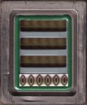
IMG_0633 33.jpg
~
The green adhesive is the seal on the diode chamber window. I removed the gang lens by cutting it's adhesive with a razor blade. By the way, the gang lens is quite brittle.
 
So there's a flat glass window under the gang lens that spans all the dies ?

This opens up re-lensing, correction and knife edging possibilities but it's a lot of work and maybe custom optics.........you might could just use rows of FAC lens and then a new grid of lenses that could zoom as a unit.......
 
How did you remove the glue that holds the lens? I want to try to refocus my array for a tighter focus.
 
So there's a flat glass window under the gang lens that spans all the dies ?
yes, coated of course

This opens up re-lensing, correction and knife edging possibilities but it's a lot of work and maybe custom optics.........you might could just use rows of FAC lens and then a new grid of lenses that could zoom as a unit.......
Ezackly
I need to decide which configuration to undertake and leave half done.
 
How did you remove the glue that holds the lens? I want to try to refocus my array for a tighter focus.

Optional: draw around the lens array with a permanent marker if you will want to reattach the lens array later on. The alignment of the lens array, with the diodes underneath, must be very precise and this might simplify matters a little. A few small spots of UV activated adhesive around the edge of the lens array can hold it in place and is not difficult to remove if used sparingly. Getting the alignment exact can be challenging. Note the thickness of the adhesive under the lens array edges. It determines the distance from the diodes to the lenses!

Use new single edge razor blade, or razor knife, or one which is at least very sharp. A regular knife blade is too think and may break the glass. It is helpful, but not required, to have the device immobilized so it does not move around while working. Be aware that the lens array is quite brittle. It is important to cut through the adhesive to separate the lens array. Do not try to separate the adhesive from the glass or pry upward on it. The adhesive is not epoxy, I suspect that it is polyurethane, it is strong synthetic rubber. It is harder than silicone sealer. When cutting, move the blade slowly and use substantial force. Expect to use several passes to cut through the adhesive.
The first cut will be vertical and right next to the glass, to cut off the adhesive that is next to the glass. Do the same on the other side. Next, cut horizontally, undercutting the adhesive adjacent to the glass. If required, make a number of cuts, to get most of the adhesive off the metal underneath. Do the same thing on the other side.
The next cuts require more care and will separate the glass from the metal underneath. This adhesive is not very thick here, so care must be taken to avoid putting too much pressure on the glass. Make sure the blade is horizontal and undercut the adhesive. Again multiple passes will be needed to do this safely. After removing the lens array, scrape off remaining adhesive. A sharp knife is not needed here. Be half-way careful though because the metal is quite thin and dents easily. This is not the only was to do this, but it is what I did. Very fine "music wire" might be able to do the cutting, but it did not occur to me at the time.

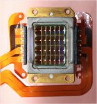
Before After NUBM34 2.jpg
 
Last edited:
Thank you for sharing this.

I was extremely worried about the dust from cutting would get into the array. However, you shared above that there is a window to protect the array/mirrors. I am more confident in pursuing this now. I had initially thought you used some kind of chemical to soften the glue to avoid and production of dust.

I have multiple micrometer XYZ axis holders so I should be able to position it again.
What type of glue do you recommend? I have basic high viscosity UV glue cured by 350nm from loctite. I am wondering if you know of any more specific glues I should use for this precision job.
 
Thank you for pictures, Tedcs !

ikevvii, what kind of XYZ holders do you have? Can you post a picture?

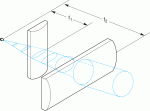
To my uderstanding if one does not like the gang multilens output, the professional way of shaping the beams would be to put long and thin cylindrical PCV lenses side by side in front and anlong of each LD row (in the cross shape, so each beam would be shaped as in this pic).

But of course this is difficult, since we would need to mesure divergence of the beams in both axis, and then manufacture custom Cylindrical lenses with focal distances needed.

CKXLENSE-S-600w.gif


Back
Top