Welcome to Laser Pointer Forums - discuss green laser pointers, blue laser pointers, and all types of lasers

LPF Donation via Stripe | LPF Donation - Other Methods

Links below open in new window

ArcticMyst Security by Avery

My DIY phase change system :D

Things

0
Joined
May 1, 2007
Messages
7,517
Points
0
Circuitry all mounted up and running :)

Just a few code problems, and it needs a bit of EMI shielding, but nothing major.

Originally I was using a 250VAC 17A relay, but it died after about 3 shots. Checking the LRA of the compressor (Locked rotor amps) showed that the compressor draws about 47A on startup, wayyyy too much for my relay! So I replaced it with a much beefier 250VAC 30A relay, with 10kV 65A inrush ratings.

IMG_1520.jpg


diachi

0
Joined
Feb 22, 2008
Messages
9,700
Points
113
Nice job! I'm impressed. What are you using as the microcontroller? Looks like an arduino with a linear PSU on the same board.
 

Things

0
Joined
May 1, 2007
Messages
7,517
Points
0
It's an ATMega168 with the Arduino bootloader :)

Got the code figured out, it now counts down in seconds until startup.

Still have the EMI problem though, I need to find some metal screen or something and build a box over the circuitry.
 

HIMNL9

0
Joined
May 26, 2009
Messages
5,318
Points
0
If i can give you a pair of suggestions .....

Use a common ground for all the circuitry, keep the relais away from it, with only the wires that goes to it from the board, abund with filtering capacitors on the circuit (not just at the PSU, also here and there on the circuit), and ofcourse, place a diode in reverse protection, in parallel to the relais coil ..... and also ark breakers on the relais contacts (simple 47 ohm 1W resistor in serie with a 100nF 450VAC, placed in parallel to the contact of the relay ..... one for each contact if you cut both the wires, just one if you cut just one wire, they also prevent the contacts to be "cooked" too much) ..... and check that the PSU can drive the relais coil without problems ..... if you can, maybe also decoupling the two power lines can help a lot, i mean, from the psu, one line with its own capacitors go to the relais and through the power transistor that you use for drive it, another line with its own capacitors go to the power of the logic and controls, through 2 different diodes, with only the ground in common .....

After this, you can also place a small iron container around your circuit (except the relais, ofcourse).

BTW, nice unit ..... :beer:
 

Things

0
Joined
May 1, 2007
Messages
7,517
Points
0
I did consider the kickback from the relay, and there's a real possibility thats my problem. I'll chuck some diodes and capacitors on it and see what happens.

Thanks for the tips, should be able to get it sorted out :)
 

Things

0
Joined
May 1, 2007
Messages
7,517
Points
0
Ok, just did a test. I connected the relay to a different power supply, powered up the AC unit and controller, and activated the relay from the seperate power supply, and the uC didn't drop out. I tried it 3 times and the microcontroller didn't drop out once. So either the surge current of the relay coil on startup is depriving the microcontroller of power, or something is making it back from my relay into my circuit.
 

HIMNL9

0
Joined
May 26, 2009
Messages
5,318
Points
0
Probably you can solve the thing also using a single PSU, if you found one of those 12V 700ma or 1A "wall" power supplies ..... i meant with a connection like this one:

attachment.php


Also, place the diode in parallel of the relais coil directly on the relais, keep it away from the rest of the circuit (you can place it near the motor and wire it to the rest of the circuit with two wires "whirled" together) ..... and for the arc breakers, the RC serie go connected in that way .....

BTW, i saved the draw before realize this, ..... you can also improve the filtering, placing a ceramic 100nF capacitor in parallel to each electrolitic one ..... where instead, for the arc breaker, you need to use mylar or polyester capacitors, ceramics are not so good for that use.
 

Attachments

  • mcu cooler.jpg
    mcu cooler.jpg
    54.6 KB · Views: 1,446

Things

0
Joined
May 1, 2007
Messages
7,517
Points
0
I tried putting a ceramic cap and diode right on the relay, and a diode on the PCB, and a ceramic cap on the gate of the uC. It did look promising like 2 times, but started glitching again :(

I'll throw a few more capacitors on the power supply and try your idea's.
 

Things

0
Joined
May 1, 2007
Messages
7,517
Points
0
OK well, that was odd ... It switched it, and it didn't glitch, but instead glitched like 20 seconds later ...

This is getting really annoying ... :(

Although, whatever I have done has improved it a lot, it's only occasionally it glitches now. I have a feeling this may be reliant on the time when it switches during the mains sinewave. If it switches at a peak, the EMP is going to be much larger than if it switched at 0V and then ramped up.

I added a mains cap in parallel to the transformer, a lot more capacitance to the power supply (2200uF more after the bridge rectifier, 1200uF more after the 7805), added an electrolytic cap to the relay as well, as well as a capacitor on the relay connecting on the PCB, and a small ceramic capacitor on the temperature sensor wire (It runs inside the unit too).

Like I said, it's much better now than before, however the glitches seem to be random. Sometimes it'll switch on fine maybe 3 times, then glitch on the 4th, or it may glitch on the first start. I'm thinking it's definitely something to do with the AC sinewave ..

EDIT: Just tried it again from a seperate bench PSU and it still glitched, meaning it's not the relay causing the problems. Now I'm really lost :(

EDIT AGAIN: Just tried running all the circuitry off a seperate bench PSU, getting all the mains off the circuit board, and it STILL glitches!

I am extremely stumped as to what's going on here ....
 
Last edited:

HIMNL9

0
Joined
May 26, 2009
Messages
5,318
Points
0
Uhm, this make me think that, with these currents, you're right about the "non-zero-crossing" switching time idea of the relay ..... but, for solve this, the only way is to use an electronic relay (no matter if self-built or an already ready "brick type" one, but there's no relais quick enough, must be a solid state device).

Something like this one, or similars, probably ..... or self-made using an optotriac as trigger, like the MOC3041, driving a high power triac like this one, or similars ..... just as ideas .....


EDIT: if is not a secret, can you post a schematic of the setup that you are using, so i can try to imagine what is the problem ? ..... and what exactly it do, when it "glitch" ? .....
 

Things

0
Joined
May 1, 2007
Messages
7,517
Points
0
This is the glitch: YouTube - Temp controlled oversized water cooler problem

I made up a diagram too:

schem.png


I'm wondering whether it's the uC or just the LCD screwing up. I can't really tell, but it seems something on the LCD changes when a press the button, meaning the code loop is still running.

EDIT: I tried flipping the lid upside down (The one the PCB is sitting on), grounded it. So there was a peice of grounded sheet metal between the compressor/fan etc and the PCB, and it STILL glitched. Something else is going on here :(

EDIT: I just re-made the code so it resets the LCD after it switches the relay, this, although hacky, has fixed the problem :)

Cheers,
Dan
 
Last edited:

HIMNL9

0
Joined
May 26, 2009
Messages
5,318
Points
0
LOL ..... well, it's a solution, more or less :p .....

I was considering the possibility of a return through the main line, and trying to redraw a wiring diagram, but had not too much time, til now (clients in the shop) ..... if i reach to do it, i will post it, or tomorrow maybe .....
 

Things

0
Joined
May 1, 2007
Messages
7,517
Points
0
Here we go, did an overview of it :)
http://www.youtube.com/watch?v=2srwqPjCp8s

I discovered something .. the LCD glitches sometimes when I plug other stuff into the same power board as the aircon unit. Maybe I'll put an EMI filter on the whole AC or something.
 
Last edited:

HIMNL9

0
Joined
May 26, 2009
Messages
5,318
Points
0
Uhm ..... i see something strange, in the circuit, but more than errors, it can be drawing mistakes .....

First, the reset pin of the ATmega, is active low ? (means, you must put it low for reset ?) ..... if yes, R1 as 10kohm, and an 1uf capacitor between this pin and the ground, ensure you an automatic reset each time you power up the system ..... also, no bounce filters, on the two buttons ? ..... is always better place an RC also there, for take care about disturbs and bounces .....

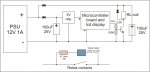
The mosfet that drive the relay ..... is really connected in that way ? ..... no resistor on the led, and the mosfet connected directly to the atmega output pin ? ..... and the LM335 seem reversed, but this can be just a drawing error ..... just impressions, anyway.

Can you try to wire all in this way, if you want ? .....

attachment.php


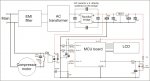
The tracks in bold, means using wires of big section (size), and the GND line is better if is more "robust" of all the rest, too ..... the diodes can be 1N400X serie ..... the LM336 is better wired in this way, so you can adjust it more precisely (and also it cannot become overstressed from current, cause the maximum current that it can hold in safe range, is only 5mA) ..... the EMI filter can be took from any old PC PSU, if you don't want to wind manually the double-wires coil ..... also (but this depend from the relay coil resistance), a resistor can be added in serie from the coil to the positive ..... 22 ohm 2W can be good, but i need to know the coil resistance, for be sure ..... and don't connect the led to the gate, it cause problems ..... connect it in parallel to the coil, with its own resistor .....

Can post externally a bigger version, if the schematic is not too clear at this resolution (VB size limit, here) ..... and, i have not redrawn all the ATmega connections, sorry but it's a damn pain you-know-where, to draw electronic schematics with coreldraw :p :D

EDIT: also, the 4 capacitors on the bridge, is not indispensable to solder them directly to the bridge pins, just nearest possible them ;)
 

Attachments

  • cooler wiring.jpg
    cooler wiring.jpg
    107.3 KB · Views: 2,108
Last edited:
Joined
Jul 15, 2010
Messages
191
Points
0
Hi Things,

Just a thought here. What guage and length of AC mains wire are you using?
If it's too small or long of a run, you could be getting a voltage sag that's causing the glitch.

Nice project by the way! Very good looking work.:)


Top