Welcome to Laser Pointer Forums - discuss green laser pointers, blue laser pointers, and all types of lasers

Buy Site Supporter Role (remove some ads) | LPF Donations

Links below open in new window

ArcticMyst Security by Avery | Browser Hide by Avery

MIC29312 based linear driver

This:
@6.06V, test load at 3.5V it outputs 635mA stable

Suggests to me that we're actually getting a dropout voltage of 2.5V + Otherwise, you'd see the full expected current, no?


The expected current should be about 2.48A for a half ohm (1.24/.5 = 2.48A).

So, the voltage drop is probably even more drastic, but there could be more errors testing it this way. Proper heatsinking could improve outputs, lack of required capacitors could also affect the output (not sure). At lower currents its pretty dead on accurate. Until, I can test it on the PCB I can't say these will be the true values at higher currents.

The only thing that puzzles me is how cool it runs at over 1A :confused:
 
Wait- you don't have capacitors ?

That will DEFINITELY affect the output, 100%.

In fact, that will even cause 1085s to become unstable immediately. I can't tell you how many 1085 drivers I built without the output caps (intending to put SMD caps across diode leads), only to find that they didn't work as expected on test loads.

With these ULDO drivers, the proper caps aren't just there to protect the laser diode, they're there to keep the driver itself stable too.
 
Yes, I noted that a few times in my earlier posts. That is why I can't guarantee the absolute values, but rather an approximate value the driver should output. I think these ICs are pretty robust that they haven't crapped out yet and still able to produce stable readings without the capacitors.

I just can't wait for the PCBs to arrive! :san:

EDIT:

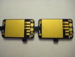
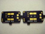
Ok, So the new PCBs are in!:D

But, I don't think I'll have time to test these out until next week or next next week. :cryyy:

It's that time of the year again, hell week.

But, I'm going to do my best to test these out as soon as possible.

Here's some pics:
attachment.php


attachment.php
 

Attachments

  • IMG_0164.JPG
    IMG_0164.JPG
    104.8 KB · Views: 242
  • IMG_0165.JPG
    IMG_0165.JPG
    112.3 KB · Views: 247
Last edited:
Ok, so it's been a few weeks now and school has been over since the 24th. I finally had time to test this driver on the PCB with input/output capacitors.

And just like my testing the driver is working and stable too!

I tested it earlier and here are some of the results:

Driver set to produce 577mA (1.24/2.15 = .5767A) using (2) 4.3 ohm SMD resistors.

Test load set for 4.2V (445/bluray):
@7.98V = 588mA
@6.07V = 322mA
@4.15V = 29.5mA
@4.03V = 29.2mA

Test load set for 2.8V (red)
@7.98V = 588mA
@6.07V = 588mA
@4.15V = 287mA
@4.03V = 255mA
 
So I don't understand - what advantage does this driver have over any other linear driver?
 
Well, the IC used has one of the lowest dropouts (0.6V @ 3A), but other than that It's just for informational purposes. I tend to post threads to document works I've done and sometimes use them in my laser builds.
 
My next plan for this driver is to make it adjustable up to 500mA only to not fry the pot.
 
The dropout of the regulator itself is very good, but remember that for the TOTAL dropout of the driver, you need to add also the one on the RSET (that is the Vref, in this regulator still 1.24V)


Back
Top