Welcome to Laser Pointer Forums - discuss green laser pointers, blue laser pointers, and all types of lasers

Buy Site Supporter Role (remove some ads) | LPF Donations

Links below open in new window

FrozenGate by Avery

LM317 based driver for 1W 445

hi guys, a quick question, is it ok to connect the tab on the lm317 to the same heatsink than the 445 diode?, I was checking the diode and looks like isulated from the case, is that correct?

quick answer apreciatted, I'm setting up a quick lab for my diode just now, by the way, which driver with modulation and cheap could you recommend for a 7-13v range power?
thanks very much

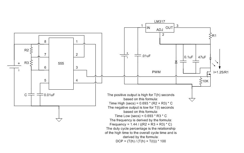
If the case pin is not connected then yes you can. For modulation you could use a LM317 and a Nfet as a low side switch.


thanks, do you have a diagram for an example in how to put the fet? what would you use for oscilator?
 
thanks, do you have a diagram for an example in how to put the fet? what would you use for oscilator?


Double check my work I just made it quick but here

lm317555.jpg
 
Last edited:
ok, so I made a quick lm317 DDL circuit with a 1ohm-5W which is really 1.3ohms resistor that I got laying around, tried running it with a test load with 8 nimh 2.9A batteries but where not fully charged and voltage was dropping under 8v, so output was really low at 560mA, then I plugged in a 12v pack and got 1.24A output which was not really expected with a 1.3ohm resistor, I was shooting for a bit under 1A, but well.. 1.2 was what I originally wanted to drive the laser at, so, unexpected power but is what I wanted, so, left it there, mounted it in a heatsink and connected the laser to it.
it will start warming a little only after a few minutes, but was only a very quick setup anyways, very powerful tho and now I can play for much longer time.
so, that means... now I can run my laser with my diving lights packs which are 12v 4.5A nimh and 11.1v 7.8A Li-Io with no problems :)

I was using the NJG-18 before, but it sucks too much juice for a single battery and the protection inside the battery was kicking on and turning the power off.

at 10' the smallest I can get the dot with the aixiz glass is a little less than 1cm, which is much bigger than I expected, but will burn wood really quick :)

my setup still ugly, but working really good now

thanks for the help, will try the modulator some time, I didn't know I can get the freq that high with the 555
 
Interesting thought -

If you wanted to run from 12V, and assuming you didn't have a 6W power resistor laying around ;) couldn't you use two (2) different LM317 DDL circuits, one "inside" the other?

Wire them both for your desired current, except the output from one DDL circuit merely serves as the input for the next entirely closed DDL circuit?

In effect, you'd be using the first LM317 to drop 12V down to ~9V, and then the second LM317 to drop the 9V down to the diode's Vf. Basically, you'd be separating the heat dissipation between two ICs.

It's not the most elegant solution, but if someone doesn't have a ton of surplus parts around, and has perhaps just ordered some LM317s and a few current setting resistors for their first build - might this approach not be pretty workable?
 
Last edited:
ok, so I made a quick lm317 DDL circuit with a 1ohm-5W which is really 1.3ohms resistor that I got laying around, tried running it with a test load with 8 nimh 2.9A batteries but where not fully charged and voltage was dropping under 8v, so output was really low at 560mA, then I plugged in a 12v pack and got 1.24A output which was not really expected with a 1.3ohm resistor, I was shooting for a bit under 1A, but well.. 1.2 was what I originally wanted to drive the laser at, so, unexpected power but is what I wanted, so, left it there, mounted it in a heatsink and connected the laser to it.
it will start warming a little only after a few minutes, but was only a very quick setup anyways, very powerful tho and now I can play for much longer time.
so, that means... now I can run my laser with my diving lights packs which are 12v 4.5A nimh and 11.1v 7.8A Li-Io with no problems :)

I was using the NJG-18 before, but it sucks too much juice for a single battery and the protection inside the battery was kicking on and turning the power off.

at 10' the smallest I can get the dot with the aixiz glass is a little less than 1cm, which is much bigger than I expected, but will burn wood really quick :)

my setup still ugly, but working really good now

thanks for the help, will try the modulator some time, I didn't know I can get the freq that high with the 555

You 1.3 ohm resistor is probably 1 ohm the .3 is probably wire error and meter resistance. The 555 can go up to 2mhz depending on the manufacturer and source or sink ~200mA. These are multimode diodes so expect a big dot. Sounds like your nimh batteries could not source the current required that is common.
 
Interesting thought -

If you wanted to run from 12V, and assuming you didn't have a 6W power resistor laying around ;) couldn't you use two (2) different LM317 DDL circuits, one "inside" the other?

Wire them both for your desired current, except the output from one DDL circuit merely serves as the input for the next entirely closed DDL circuit?

In effect, you'd be using the first LM317 to drop 12V down to ~9V, and then the second LM317 to drop the 9V down to the diode's Vf. Basically, you'd be separating the heat dissipation between two ICs.

It's not the most elegant solution, but if someone doesn't have a ton of surplus parts around, and has perhaps just ordered some LM317s and a few current setting resistors for their first build - might this approach not be pretty workable?


If I did not have any big power resistors around I would wire 2 LM317s in parallel and set each one for 1/2 of my total desired current.
 
^^^^^^........
For that to work as you'd expectet, you mustn't forget to add a low (<1) ohm balancing resistor in series
after every LM317's output before you join them together.
 
I'm pretty sure the resistor is 1.3 ohm, the meter meassures accurate. there is no need really for 2 lm317, it does not heat that much, the total heat would be about the same at the end.

the nimh batteries I used are 2.9 amps, and they do supply enough power because I use them in my 10w HID backup light, will retest tonight, I charged them up lastnite, so, lets see, look like the lm doesn't like to go under 8v.
 
Last edited:
the resistor is 1.3 ohm, the meter meassures accurate. there is no need really for 2 lm317, it does not heat that much, the total heat would be about the same at the end.

the nimh batteries I used are 2.9 amps, and they do supply enough power because I use them in my 10w HID backup light, will retest tonight, I charged them up lastnite, so, lets see, look like the lm doesn't like to go under 8v.

If your resistor is 1.3 you should get 0.96A out you are getting 1.24A that would indicate you have a 1.008ohm resistor. Are you using probes to measure the resistor? Are the probes soldered to the resistor to remove error due to surface contamination? Is it a milliohm meter?
 
Maybe someone can explain to me how this doesn't kill the diode.

When the fet is off, the cap in parallel is charged to 10V (if you're running the lm317 on 12V) Mosfet turns on... doesn't anyone else see a problem with that?
 
Maybe someone can explain to me how this doesn't kill the diode.

When the fet is off, the cap in parallel is charged to 10V (if you're running the lm317 on 12V) Mosfet turns on... doesn't anyone else see a problem with that?

Good call thanks for double checking my work. The cap should be || with the LD I will fix the pic later after work. Might even be a good idea to add a second larger cap in || like I said after I posted it I did it quick tell me if you see errors.
 
Hey if you are still interested in using the computer PSU as a voltage supply to the driver checkout a thread I made under my profile with some info on turning a PSU into a variable PSU, I built one recently using the ground and yellow +12V wire going into a circuit similar to the LM317 circuit used as a driver, from there you then get a variable bench powersupply between 1.5-12V :) perfect for testing/powering drivers at any voltage you need.

I didn't read the whole thread so I'm not 100% sure on what's been discussed but if you still want to use the LM317 circuit to drive you diode I'd suggest you use an LM350 instead if you can get a hold of it, it's identical to the 317 except it'll handle upto 3A rather than 1.5A.

Also I'd strongly recommend using a heat sink, on mine I just used a finned heatsink I pulled of an old motherboard.
 
Maybe someone can explain to me how this doesn't kill the diode.

When the fet is off, the cap in parallel is charged to 10V (if you're running the lm317 on 12V) Mosfet turns on... doesn't anyone else see a problem with that?


Updated let me know if I missed another thing

lm317555.jpg
 
I have little/no experience with PWM, but are you sure about that much capacitance across the diode? At a higher modulation rate the cap will absorb the pulses and you'll just get a wiggling output rather than a pulsing output.
 
Last edited:


Back
Top