Welcome to Laser Pointer Forums - discuss green laser pointers, blue laser pointers, and all types of lasers

LPF Donation via Stripe | LPF Donation - Other Methods

Links below open in new window

ArcticMyst Security by Avery

Killed my C6, ugh :(

Joined
Nov 2, 2012
Messages
626
Points
43
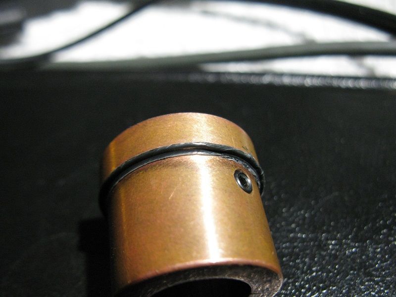
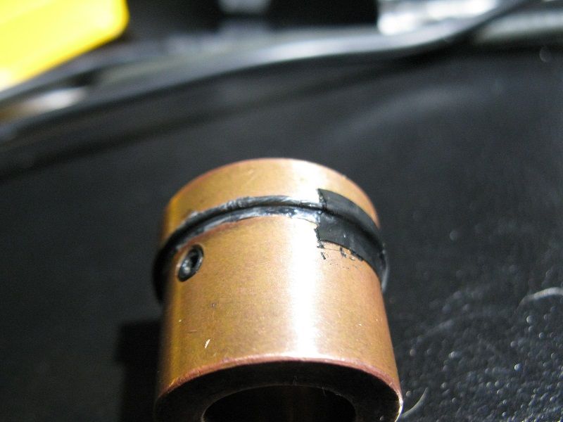
I replaced the teflon tape on the lens threads and was tightening down the lens and for some reason it caused the heatsink to spin inside the host. Didn't even notice it until the laser didn't turn on. Turns out it snapped the pins off the diode.

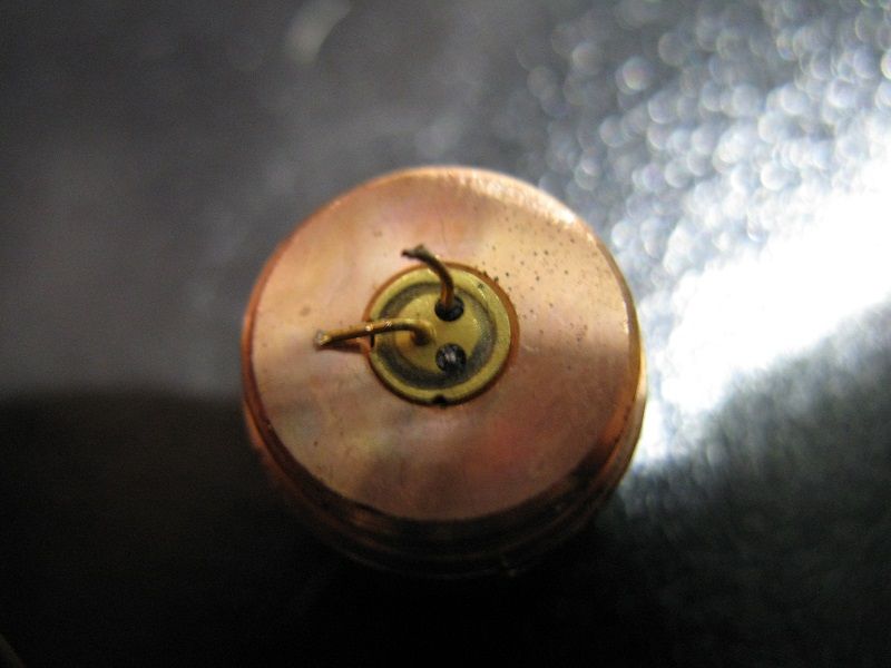
Nothing I can do about it, the pin is snapped off at the diode and there is no way in hell I can work on something this TINY. I have no idea how you guys do it, the driver and connections are so small I can barely even see them.

Well, now what? I guess I could order a new diode and driver and drop them in, but what a bummer, seriously. I think this might be the wrong hobby for me.

Sigh :(

eta: according to my multimeter, the driver is still good, still puts out voltage at the diode end. Should I try replacing the diode alone? I don't have the tools to work on this, my soldering iron tip is absolutely huge compared to even the largest feature on the driver board. It is so SMALL, I had no idea how small until now. I absolutely do not have the tools to work on this.
 
Last edited:


Joined
Mar 29, 2013
Messages
1,221
Points
63
If you want to send the diode to me I will see if I can fix it :)

Are both pins or only one snapped?

I will cover return shipping fixed or not.

That's Is how I felt when I killed my laser. I felt that I should quit the hobby, but that feeling passes.

PM me if you are interested ;)

:beer:
-Matt
 
Last edited:
Joined
Jul 4, 2012
Messages
2,834
Points
63
Have any pics? Its possible to soldier wires back onto snapped pins if they still have nubs-- not easy, but possible.
 
Joined
Nov 2, 2012
Messages
626
Points
43
It's only one pin snapped off, but it's snapped off AT the diode, there is nothing at all left.

Stand by for picture.

ETA: Photo is below. To me, that is unfixable, I would need something like a robot with microsurgical precision to be able to have any hope of fixing that. The driver and diode are smaller than I could have possibly imagined, my hands shake so much even on a good day I would need a robot to work on something so small.

snappedpin_zps3edbc136.jpg
 
Last edited:
Joined
Mar 13, 2013
Messages
315
Points
0
If only one pin is off and the diode is case neutral or the pin even was the case pin you can connect the pin carefully and fast with a small solder blob to the case.

Then you need the same case polarity of your host and the constant pole of your driver to have the same polarity. ( most are negative constant some like amc7135 are positive constant) :)

edit: I just saw that you have only an opnext diode c6 listed in your sign so I opened the dataaheet and now I'm waiting for the photo to say more :beer:
 
Last edited:
Joined
Nov 2, 2012
Messages
626
Points
43
I added the photo to my previous post, tell me what you think of that....

Honestly, my inclination is to order the diode/module with no leads attached and use a diode socket (like Lazeerer in his recent 488nm build), not sure if that would work or not. I definitely wouldn't trust my soldering skills on any day to work on something so small, even fixing through-hole technology (as in my Metrologic HeNe) is, to me, precision work.
 
Last edited:
Joined
Feb 5, 2008
Messages
6,252
Points
83
I think that the one that snapped it one of important ones. You only need two out of three but unfortunately I think this one you need.

Just to be sure, what wavelenght was the diode?
 
Joined
Nov 2, 2012
Messages
626
Points
43
Do you know which case polarity (battery pole at tailcap) and driver is used in your c6?

It is (was) case negative.

Eudaimonium said:
I think that the one that snapped it one of important ones. You only need two out of three but unfortunately I think this one you need.

Just to be sure, what wavelenght was the diode?

Opnext 638nm 120mW driven at 300mA.

It might actually be the negative pin that broke, the other pin was attached to a solder point marked "+5" although it is so small I can't see it. I'm looking at it under a 10X magnifier and I can still barely make anything out.
 
Last edited:
Joined
Mar 13, 2013
Messages
315
Points
0
It is (was) case negative.


Opnext 638nm 120mW driven at 300mA.

It might actually be the negative pin that broke, the other pin was attached to a solder point marked "+5" although it is so small I can't see it. I'm looking at it under a 10X magnifier and I can still barely make anything out.

From what I see you've been unlucky twice :/
In the datasheet it says that the pin broke the positive pin so you could restore
the connection by a solder blob over the end of the broken pin but that would make the diode case positive which would not match to your case negative host.
And if you would switch the case polarity you would need a new positive constant driver.

I see two choices of using it in the future

1. change your driver to a positive constant driver and case polarity simply turning the batteries that way would save your c6

2. use the driver and a lab heatsink or the c6 heatsink as a neutral heatsink with a wall power supply or a battery holder to make a lab laser

:beer:
 
Joined
Nov 2, 2012
Messages
626
Points
43
That is what I determined according to the pinout, it is the positive pin that broke.

Bugger. I have no idea why the damn heatsink decided to spin, it shouldn't have been able to. I think I'm going to just order a new diode and module and see what I can do with it, or maybe I should go for new diode and driver both?

I could maybe solder a new diode onto it but there is a risk of hooking it up backwards because I can't tell which terminal on the driver is which. And then too, the tiny size of it... I would need surgical precision to do it.

Looks like my first "build" is going to come sooner than expected.

Maybe someone could fix it for me? I don't know, I feel like since I broke it, I should be the one to fix it, if that makes sense.
 
Joined
Feb 5, 2008
Messages
6,252
Points
83
For the spinning heatsink problem, it's usually because it's machined with minimal tolerance.

Host's internal dimensions vary so wildly that it's impossible to make a perfect heatsink that just fits like a glove.

You can make one perfect sink, for one perfect host, and put it another host of the same model and it may rattle or not fit. That's why I always go with 1, or sometimes even two milimeters too long heatsinks. There may be a gap in the thread at the end, but it'll work for sure.

Psst, pro tip.

I have found that a few strategically placed O-rings can make wonders our of an imperfect sink. Fixes it in place real good.
 
Joined
Mar 13, 2013
Messages
315
Points
0
If you decide to build a new laser.
you should keep the diode and try the solder blob method and build yourself a small little lablaser maybe with a cheap lm317 driver ;)

Btw why can't you tell your drivers output polarity normally there are small etched marks on the driver board, the connecting wires are black and red and you could check it with a cheap DMM.:beer:
 
Joined
Nov 2, 2012
Messages
626
Points
43
If you decide to build a new laser.
you should keep the diode and try the solder blob method and build yourself a small little lablaser maybe with a cheap lm317 driver ;)

Btw why can't you tell your drivers output polarity normally there are small etched marks on the driver board, the connecting wires are black and red and you could check it with a cheap DMM.:beer:

It's just too small, I'm getting double vision just trying to see it.

The good news is that the driver output polarity is no longer in question, I checked it on my meter and it's definitely the + pin that broke. I could probably solder leads to the terminals if I sharpened my soldering iron tip to a sharp point. Or, you know, just bought a proper very sharp tip, heh.

eta: assuming I didn't kill the driver by checking it with the meter... bleh... klutzy, klutzy, klutzy....

Don't really trust myself to do it, at least not 100%, but at this point I do believe I could buy a new diode and solder leads to the driver output. Or maybe order a diode socket, solder that to the driver, and just order the diode in module with no leads.

I like the idea of the diode socket a la Lazeerer's 488nm build. What do you all think?

See, this is why I think Western builds are the best. They are FIXABLE, maybe even fixable by a dunder-head like myself :p One thing is for sure, I've learned a LOT just from this incident, maybe it was meant for a good cause.
 
Last edited:
Joined
Nov 2, 2012
Messages
626
Points
43
Okay, change of plans. I have decided to leave the electronics repair in the capable hands of DTR. I just don't have the right tools to work with this stuff, my tools are too big and the electronics are too small. Time to look into getting a smaller soldering iron, at the very least, and probably something to hold stuff and free up my hands. Will absolutely need it if I am to do my own builds at some point. Lesson learned!

In the meantime, I investigated the host and heatsink situation more closely, to see why the heatsink was able to spin, and whether I could find a way to prevent it. Here is what I found:

Comparing the heatsink in Cheech's laser to the heatsink I got from Survival Lasers, it's clear that the "rim" on the SL heatsink is about 1mm taller than the one in Cheech's laser. This is nobody's fault; it's just something that can happen with the custom-made parts, I suppose. The taller rim explains why the SL heatsink was resistant to spinning in both C6 hosts, while the other heatsink would rattle and spin freely in both hosts. For some reason, it did not rattle when the driver and leads and whatnot were installed. Perhaps they put just enough pressure on the sink to prevent it from rattling and give me the illusion that the heatsink was solidly in place.

Clearly I need a way to hold that heatsink in place, and what's more I need whatever holds it to be on the bottom, so that turning down the top bezel and/or tightening the lens doesn't cause the sink to spin.

Eudaimonium suggested I need an o-ring somewhere to make that heatsink spin-proof. I don't have a proper sized o-ring on me, so I made myself an o-ring out of some teflon tape. I twisted the teflon tape up as tight as I could, wrapped it around the heatsink rim, and secured it into place with a bit of electrical tape. Dropped the heatsink back into the C6 middle tube and tightened down the top bezel, and it worked. No matter how much torsion I put on the heatsink now, it simply will not rotate. It certainly didn't rotate as I tightened down the top ring. Best of all, when I removed the top ring again, all it took was a gentle tug and the heatsink popped right back out, no forcing required.

I believe I will use that when I receive the repaired module back. In the meantime, while I didn't learn as much as I'd hoped about the electronics side of things, I definitely learned more about the C6 host and its quirks. That, without a doubt, will be of use to me in future projects, and IMHO nothing is a total failure as long as *some* knowledge came out of it. I don't believe I'll be leaving this hobby after all; the defeated feeling does pass. Thank you for all of your encouragement! :)

Here is the picture of the rigged-up o-ring, made of twisted-up teflon tape. The piece of electrical tape was bigger but I trimmed it down once the o-ring was secured.

c6heatsinko-ring1_zpsab641ce4.jpg


c6heatsinko-ring2_zpsc42861ea.jpg
 
Joined
Sep 12, 2007
Messages
9,399
Points
113
I would take the remaining "unused" pin, bend it over so the tip is touching or almost touching the "positive pin." Then add flux and a dab of solder to fill in the gap. If it works, you now have an electrically and mechanically sound pin to solder the driver lead to. This extra pin will be either for nothing, or for a photodiode, so who cares if that gets blown up.
 
Last edited:


Top