Welcome to Laser Pointer Forums - discuss green laser pointers, blue laser pointers, and all types of lasers

LPF Donation via Stripe | LPF Donation - Other Methods

Links below open in new window

ArcticMyst Security by Avery

Kaidomain 50mW CR2 - inital review

Joined
Mar 2, 2008
Messages
171
Points
0
IgorT said:
I found a fix for the blinking problem at power on/off.

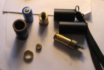
The problem is not the switch itself, but the fact, that it is not mounted in place. When you press the button, the button pushes on the battery, and the spring on the PCB alows the battery to go deeper into the body. When you release the button, the spring pushes the battery and the switch back, and the contact between the button and the body is momentarily lost.

Sometimes it just dims a bit, othertimes it blinks completelly. I glued the button in with just two drops of glue on the sides, and now this doesn't happen anymore. I like it much better now. It also helps if a spacer is put in, so that there is more pressure from the spring on the PCB, but i really don't want to put stress on it, since it is directly soldered to the LD. Luckily it is strenghtened with hot glue, so the diode doesn't get all the stress.


While tracking the new DX200 i noticed my other two KD50s arrived at the customs today. Means i should get them the day after tomorrow. The DX should come tomorrow, unless the customs send a letter asking for the invoice. That could cause a painfull delay.

I think if you ordered the DX red 200 as well, you'll find it is much better engineered with regards to the clicky switch. It screws in, which is very nice and alleviates any problems to do with pressure. I may solder the switch down in my KD 50, good idea or no? Maybe if you could find another click switch, and use a tap to add a thread for it, it would be very nice.

In fact, all you need is an aluminium shim of some sort that will screw in and hold. Like a circlip but threaded.


IgorT

0
Joined
Oct 24, 2007
Messages
4,177
Points
0
bob1122 said:
I think if you ordered the DX red 200 as well, you'll find it is much better engineered with regards to the clicky switch. It screws in, which is very nice and alleviates any problems to do with pressure.

I ordered a second DX200 green. The first was mode hopping and i'm currently rebuilding it, and waiting for the power meter, for final finetuning.

In that one, the button on the PCB is a major design flaw. The PCB is directly attached to the legs of the pump diode, and nothing else holds it in place. Whenever you press the button, you put stress on the LD and bend the PCB down. To make matters worse, there is a spring going up from the PCB to the body, for electrical contact, and pushes the PCB down some more. As a result, the battery contact spring is not in the middle of the body, but bent down together with the PCB. In mine, this got so bad, that pressure on the button caused misalignment and mode hopping. By varying the pressure on the button i could actually make it go back to TEM00.

So in the end i supported the PCB by sticking a piece of plastic under the big power transistor on the lower side of the PCB, and the laser became much more stable.

For the second one i arranged with Rain at DX to test it for me, before shipping it, and also to wrap it in some additional protective wrapping.


Otherwise, i don't want to buy a <200 red with an unknown diode and without knowing, if it even has a proper driver circuit (most DX lasers don't, and the current depends directly on the battery voltage). I prefer making my own reds. This way i know exactly what i have, and i love building stuff. I'm currently making a tiny portable Peltier cooled 300mW laser, and it's gonna cost me the same in material, than that one would, and provide almost twice the power.

But i do love certain 1AA DX flashlights and will use them as hosts for my next few red lasers, with a boost circuit as a driver. I like the fact, that they are so small and some of them look very attractive.


I may solder the switch down in my KD 50, good idea or no? Maybe if you could find another click switch, and use a tap to add a thread for it, it would be very nice. In fact, all you need is an aluminium shim of some sort that will screw in and hold. Like a circlip but threaded.

Is yours blinking too? There is nothing wrong with this switch, as long as it stays in place. putting a spacer between the PCB spring and the battery would solve the problem. Soldering the switch into the brass body would be hard. Whatever you do, make sure it has a low profile, so that the battery nipple can still touch the middle of the switch.
 
Joined
Mar 2, 2008
Messages
171
Points
0
It doesn't blink, it does get dimmer and brighter if that's what you mean. Soldering the switch in is not too much of a problem I would say. I can't find my solder gun so that will have to wait (I improvised, with naught better than DX's own butane blowtorch SKU 3425 and an old 2mm allen key but it's far from precise).

Putting a spacer between the PCB spring and the battery will not actually alleviate the stress that pressing the switch will put on the diode. The whole assembly is still free to move, remember. What I did to fix that particular problem is to add solder onto the positive contact on the clicky switch then flatten it down using a battery.

There still remains the problem of stress acting on the diode each time you switch it on and off, because the switch assembly is not fixed to the casing (in the DX 200 it's screwed in so there is no issue). This is what I meant, and soldering it in is one way to solve it. The best way would be to find a screw in tailcap, but I don't know the odds of finding one of those. The only thing that acts to damp/absorb this pressure is the battery spring. I stretched mine out to make doubly sure, for the time being.
 

IgorT

0
Joined
Oct 24, 2007
Messages
4,177
Points
0
Benm said:
I'll try to take some pics while mucking with it.

Thanks! They might come in very handy... It's good to know what to expect, when taking it appart.


As for the batteries: i just got them from kaidomain too, i ordered these:

The ones i actually got are blue, not green, and only marked "CR2 3.6V 600mAh", no further info on brand, chemistry etc. They do a good job powering the laser though. Output voltage is the regular lipo 3.6 volts odd.
So you ordered 3V batteries, but got 3.6V ones? The page says they are 3V, which is why i didn't order them.

The DX 3V CR2s can be charged up to 3.6V but this immediatelly drops to around 3.3V..

If yours charge up to 4.2V, then they are a 3.6V Li-Pos. If you only charge them up to 3.6V then they are 3V batteries, which would explain the current you measured. Are the cut-off voltages specified on the label? My DX 3V CR2s say "The voltage of full charge and cut off discharge are 3.6V and 2.0V." What charger and what setting are you using?


Oh, and BTW the DX CR2s also come in 800 and 600mAh, seemingly randomly. I got the 800mAh, and someone else who ordered at the same time got 600mAh. But i have a feeling they are the same and over specd anyway.


I did manage to find true 3.6V CR2s tho, in the NewExcite Ultrafire shop: http://www.newexcite.com/shop/index.php?main_page=product_info&products_id=70
 

IgorT

0
Joined
Oct 24, 2007
Messages
4,177
Points
0
bob1122 said:
It doesn't blink, it does get dimmer and brighter if that's what you mean. Soldering the switch in is not too much of a problem I would say. I can't find my solder gun so that will have to wait (I improvised, with naught better than DX's own butane blowtorch SKU 3425 and an old 2mm allen key but it's far from precise).

Well, if you have a powerfull solder gun, it would probably work. My soldering iron is meant for fine electronics, and can not heat up such a massive chunk of metal to solder melting temperature.

Mine does dim sometimes, and other times it blinks. Power on/off is where the diode is under most stress, so i don't like switching my lasers on and off all the time. And the blinking meant it was as if i turned the laser on/off/on when i turned it on, and off/on/off when i turned it off. I really don't want to do that to it.


There still remains the problem of stress acting on the diode each time you switch it on and off, because the switch assembly is not fixed to the casing (in the DX 200 it's screwed in so there is no issue). This is what I meant, and soldering it in is one way to solve it.

I think, that in the case of the KD50, the hot glue around the PCB prevents putting too much stress on the diode, but i would rather be safe than sorry, which is why i glued the switch in with two drops of glue.. It's a temporary solution, untill i find a better one and the glue is easily removable. But it works, so i'm not worried about this anymore.
 

Benm

0
Joined
Aug 16, 2007
Messages
7,896
Points
113
The CR2's i got are just normal lipo types just like the commonly sold 16340 cells but obviously a bit smaller. Charge end voltage is around 4.1 volts, and after a little use or letting them stand for a day, its 3.6v. Nothing strange if you ask me.

Here are some pics of the lasers insides... first, the pieces that come apart easily:
 

Attachments

  • kd50_pieces.jpg
    kd50_pieces.jpg
    123.6 KB · Views: 83

Benm

0
Joined
Aug 16, 2007
Messages
7,896
Points
113
After removing some white hotmelt glue, the ring around the PCB just comes off, it is not really attached to anything. It does give a good ook at the PCB this way, see pictures in the bottom left.

I proceeded to remove more hotmelt, revealing the diode leads (main picture).

Top right: looking into the laser unit from the business end. The inner piece containing the diode, crystals and first lens is actally a bit loose from the other tube. To my surprise, its also loose from the PCB, so it's possible that there is a gap eiher between diode and crystals, or between crystals and lens. I could not verify this without yanking it out which probably would have killed the laser.
 

Attachments

  • kd50_pcb_optics.jpg
    kd50_pcb_optics.jpg
    372.9 KB · Views: 84

Benm

0
Joined
Aug 16, 2007
Messages
7,896
Points
113
Removing all the hotmelt made the PCB loose from the tube. There are 2 pads on the pcb right where it touches the tube. Since it's brass, i decided to secure the pcb to the tube by soldering it in place. This works, but i would recommend against it unless you have lots of soldering experience.

Also, i secured the inner somewhat loose optics to the tube using a dash of the hotmelt i just removed. Seems to work.


Picture: Laser operating with all casing and lens removed.
 

Attachments

  • kd50_no_lens.jpg
    kd50_no_lens.jpg
    269.3 KB · Views: 75

Benm

0
Joined
Aug 16, 2007
Messages
7,896
Points
113
Finally i re-assembled the hole thing, adding a slight amout of thermal compound between the thread of the top metal ring, and between the ring and the casing it touces (around the aperture).

As you can see it still works, and optics are still messy. I did clean the inside of the second lens, and re-adjusted it for best divergence. This pic compares to a DX30 at 10 meters distance, the spill light appears worse than it actually is.


== that's it for now ==
sorry about the bad pictures, its pretty dark here.
 

Attachments

  • kd50_beam_after.jpg
    kd50_beam_after.jpg
    193.5 KB · Views: 76

IgorT

0
Joined
Oct 24, 2007
Messages
4,177
Points
0
Thanks for the pictures and the detailed description!

Benm said:
To my surprise, its also loose from the PCB, so it's possible that there is a gap eiher between diode and crystals, or between crystals and lens.

I would hope it's only loose between the crystals and the expander lens, because if it was loose between the diode and the crystals, i doubt your laser would still be working.
In the DX200, very small differences in alignment between the diode and the crystals can completelly ruin the brightness and cause mode hopping with different crazy patterns. Just pushing the button made mine change modes, depending on the pressure.


The threaded ring around the PCB unscrews in mine easily without removing the glue first. After that i can unscrew the laser module out of the top of the laser.

Did you get a good look at the diode? Is it a 5.6mm or a 9mm? Is it tightened in with a nut or is it press fit?


BTW, thanks for the info about the batteries. I'll order them. I hope i get the 3.6V Li-Pos as well.
 

Benm

0
Joined
Aug 16, 2007
Messages
7,896
Points
113
You're probably right about the space being between the crystals and first lens. I seem to have moved the first lens a bit too, the beam is now wider at the aperture, but has better divergence long distance.

DX now sells CR2 rechargeables too, so if in doubt just await some reviews there (KD doesnt seem to get that many). I just ordered another one of these lasers btw, we'll see if its different from the one i have.

Did you get a good look at the diode? Is it a 5.6mm or a 9mm? Is it tightened in with a nut or is it press fit?

Looks press fit, i think its a 5.6mm... didnt actually try to remove it though. It also has one pin that isnt connect to the pcb at all, so no optical feedback.
 

IgorT

0
Joined
Oct 24, 2007
Messages
4,177
Points
0
So it's yet another direct drive.. But i didn't expect anything else.. The DX200 has the PD connected and enough components on board to achieve PD regulation, but it simply doesn't use them. I don't see how those circuits are any better, than a resistor and a capacitor.

I'm definatelly replacing the driver in that one to a constant current source..


The KD50 started going very dim yesturday. I became worried, and thought it was dead. Especially, when i measured the battery at 2.7V and the current at 230mA. But with a fresh battery it works as new again. I really hate unregulated lasers.

I do have the DX CR2s, but they are the green 3V version. I can charge them up to 3.8V, but i don't dare go any further (to test if they could be a regular Li-Po). At this voltage, the current through the laser spikes to 390mA but quickly drops to 310..

I definatelly need to replace the circuit in this one with the AMC. It will allow me to go through the battery completelly, before the power would start to drop. But for that i will need 3.6V Li-Pos. I will need to find the best current for that. 350mA might be a bit too much, so i will probably set it at 320mA


Oh, after you told me that you got blue 3.6V CR2s, i contacted KD, and asked them if i can get them as well. Hope they know what they're selling.
 

Benm

0
Joined
Aug 16, 2007
Messages
7,896
Points
113
I think it's the same deal with the electronics in the KD - it looks like it was built to work with optical feedback, but its not connected. Perhaps the diode doesnt even have a photodiode, and the 3rd pin is internally non-connected too. Replacing the electronics with an AMC7135 sounds like a good idea, the current range is right and there is enough voltage to drop.

I'm still unsure as to why all these green lasers seem to have complex electronics but none of them seem to use it at all. It wouldnt surprise me if it was just a design that is copied from one manufacturer to the next, but somewhere down the chain some engineer decided to hack it so it works for diodes without a sensor. It would surely be cheaper just to put one single 7135 chip in, perhaps we should translate that to chinese ;p
 

IgorT

0
Joined
Oct 24, 2007
Messages
4,177
Points
0
Chimo pointed me at that thread, where you two analyzed the DX30.. I was very surprised, but it explained what i was seeing in my DX200 - current directly proportional to battery voltage.


The DX200 has a 9mm diode which definatelly has a PD. It's an open can, so i can see the PD, it reminds me of a small solar cell, and i can see the tiny wire, that goes to it. But there is no hint of regulation anywhere in there..

So, yeah, you're probably right. The KD50 even has a circuit meant for a laser pen, with the switch shorted..

But it gets better! The brass module in the DX200 and the KD50 have the exact same size, shape and the threads in the same place. The only difference is the location, where the module unscrews into two parts.

I could actually put the DX200, with circuit and all into the KD50 without any modification, and if i shorted the switch, it would work! Not only that, it would have MUCH better cooling, due to a more massive body. Especially, if i used something to make contact at the middle of the module.


I'm very tempted to switch the bodies.. But i have to find the perfect alignment first, which is very hard. It would be cool to have a <200mW green in this compact shape.


My second DX200 arrived today (the one which Rain at DX tested for me and said it was good), and of course it is mode hopping. What else. It's slightly better, than the first one, but not by much. It is obvious tho, that if this one had better heatsinking, it would work. Here the beams only split, when it gets very warm. (Probably scorching hot inside, since there is no contact between the module and the body, where it heats up the most!)

I'm sending this one back.. Don't want to have two broken ones.. Looks like the KD50 will remain my favourite for a while.. At least untill i get the CNI 150mW.. That one should be good.
 

IgorT

0
Joined
Oct 24, 2007
Messages
4,177
Points
0
Benm said:
Replacing the electronics with an AMC7135 sounds like a good idea, the current range is right and there is enough voltage to drop.

Yeah, when i first opened up the DX, i was surprised, and even slightly annoyed at the fact, that it has the positive pin at the base, but now i'm happy about it, because this allows me to use the AMC. If these IR LDs had the negative pin at the base of the diode, i wouldn't be able to.

For the KD50 i will use one AMC and for the DX200 two. Both currents actually match..


I also had a good idea, how to create an add on driver for the DX lasers.. It would be an AAA size battery shaped thing, with an AMC or two inside, a contact on both sides and a spring coming out in the middle. I would then slide a 10440 AAA sized Li-Po into the compartment and this battery shaped driver after it. On one side it would make contact with the battery negative side, on the other side it would touch the spring on the driver, and the spring in the middle would touch the body for the positive potential. It would regulate the current without the need to take the laser appart.

Such a great idea... If only the laser would be working properly. :) If the CNI should turn out to be poorly regulated, i will definatelly use it.


Oh, i forgot one thing.. when i measured the current in my second DX200 today, it suddenly turned into a 10-20mW pointer. And i was measuring in the 20A range! With the previous one, i did notice decreased preformance while measuring, but not even close to this.. The KD50 is much less affected by this, but i suppose the current is still slightly higher, than what i measured. And with full batteries i measured a stable current of around 330mA (peak 390 for a second), so i'm guessing it won't mind 350mA..


Top