Welcome to Laser Pointer Forums - discuss green laser pointers, blue laser pointers, and all types of lasers

LPF Donation via Stripe | LPF Donation - Other Methods

Links below open in new window

ArcticMyst Security by Avery

Kaidomain 50mW CR2 - inital review

Joined
Mar 2, 2008
Messages
171
Points
0
It's a bit strange. Now, the dot has even higher power (now I can't really look at it and make the shape out when pointing at my hand), but the beam is hard to see. I'm guessing that's because my room has less dust though.

When I said the exposed diode came out, I mean exposed but attached to the driver. The diode would become loose, yes, because although it's soldered to the driver board, the screw ring that holds it in place is not fixed to the diode itself (for obvious reasons). When you screw it in, you have to turn the driver and hold the screw ring, or you may twist the LD's legs.

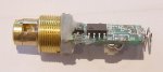
No, it's not actually press fit at all! Quite strange. Basically, the diode is passed through a slip ring (which has 3 holes, one per leg) then soldered to the driver. Meaning, that the diode is supported by its own legs, which rest on the inner surface of the holes in the slip ring - which is obviously not a good thing. It's free to move and shake around in this position, which is why they have the hot glue. The hot glue just acts to support both the diode and driver board. You can imagine the diode, and driver as a lever pivoting and resting upon a fulcrum, the fulcrum being the slip ring. The hot glue serves to fix the "lever" in place.

As for aligning it, I don't know if it's needed for that part (diode's 808nm => 1064nm) which is what came apart for me. The 1064nm=>532nm stage is fixed together with a collimator, as you saw. I lined it up by just rotating around until I got the best noise free dot, which is obviously not the best way. It worked, needless to say.

The solder joint came apart because I twisted the diode legs (I didn't know it was like this at all). And it was a cold joint anyway, so meh. You could solder the ring down. The process is a bit strange - you would have to take out the module in one piece. From the front aperture, you can see the two notches that should control the focus but seem to be welded down. With some instrument, you would unscrew it from that direction and the module will come out intact (the entire thing), leaving just the metal shell and the outer ring. From there it's just a very careful solder job and screwing it back in - you can use your fingers but tightening it will require whatever you used to loosen it in the first place, from the aperture.

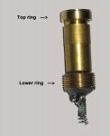
Oh, the lower ring (I presume you mean the brass ring that looks like is part of the case at first sight) is completely freely suspended, its only job is to facilitate conductivity between the housing and driver.

Edit: Now it stings my bare skin in a few seconds which it took about twice as long to do before I took it apart. Very very weird.

As far as I see, it doesn't seem to have an IR filter.

@Benm

Looking back you managed to take off the whole tube that the lens screws into? I couldn't do that, how did you manage?

Also, my lens focus seems to be fixed shut, or at least needs more torque than to pull apart the whole laser.


IgorT

0
Joined
Oct 24, 2007
Messages
4,177
Points
0
When i removed some glue around the edges, and tried to get the whole tube out of the head (the top ring was stuck in), it unscrewed in the wrong place.

Everything from the PCB to the expander lense came out in one piece.. There was still some glue around the PCB, but from what i saw, i would never have thought, that the diode would fall out, if i removed the glue.. Shouldn't the nut (the one the legs go through) hold it firmly in place?


Since you had the diode out, could you tell me, if there is some sort of lens between the diode and the crystals?


To avoid further confusion, i borrowed one of Ben's older pictures and modified it.

In two of my lasers i could make that lower ring (threaded on the outside, yeah, looks like part of the body at first) touch the laser module and push it very firmly into the head. I had to unscrew the top ring a bit for this. I would imagine, this should transfer some heat away at the diode. Especially, since the lower ring has a 45° angled inner edge, which fits the 45° angled edge of the part of the module it is now pushing against. Before i did this, it was only holding the glue..


In the best one, there is not enough place in the laser body to move the module down, for some strange reason. The spring is the shortest in this one. When i removed the glue around the edges, to make contact between the lower ring and the module, i simply couldn't. If i moved the module down a bit, so that this ring would push it back up, the battery wouldn't fit anymore.

Still, this is actually the best laser of all, even tho it has zero thermal conductivity between the module and the body at the diode. Only at the top ring. With the other two, i managed to make contact with both rings, even when the top ring got stuck in the body.. I loosened the lower ring, unscrewed the module from the top one a bit and tightened the lower one again, untill i got the best battery contact and the most pressure of the lower ring at the laser module.


In the best one, the lower ring was different. It doesn't have an angled edge, but can still push against the laser module, but i as i said, this takes some battery space away. If i turn this ring around, it can actually slide onto the laser module. With some thermal compound, this could work great for cooling at the diode. But in that case, the module would have to be even lower.

It might help if i switched these lower rings between the best one and the weird one. In the weird one i can get the module lower, and this different ring could achieve much better cooling.


Now that i see, how many differences there are between individual lasers, making general recommendations is impossible. What helped in one could make another one worse.


Bob: I'm glad, you managed to make yours even brighter, than it was before.. Looks like you found the sweet spot in the crystals. Something, that should have been done by the manufacturer..
 

Attachments

  • KD50.JPG
    KD50.JPG
    29.7 KB · Views: 73

Benm

0
Joined
Aug 16, 2007
Messages
7,896
Points
113
Strange thing with the diode coming loose.. i noticed the ring between the bottom of the diode and the circuit board, which has 2 indentations in it. The way it was assembled, i assumed the indentations were there to keep the PCB in place (relative to the tube), as it fits them exactly and was in them when i opened it up.

I still think the design of the lower ring is whacky - on mine it didnt even touch the middle tube (you can see the gap in the picture above). I'll have to see what it looks like on the next one, perhaps it does contact in some lasers.
 

IgorT

0
Joined
Oct 24, 2007
Messages
4,177
Points
0
This is what happened, when i tried to get the laser module out of the best one.
Instead of the module, i accidentally unscrewed the diode, crystal and expander assembly in one piece.

For some reason, the laser, that was the best one before, is just not the same anymore, after this. I don't understand why, since the alignment shouldn't have changed, and neither did the cooling, since i wasn't able to make contact with the lower ring..


I also noticed, that the cooling doesn't really seem to be a problem with these. The IC on the driver board gets hot, but the module doesn't. Even this small assembly doesn't get hot quickly. When it is screwed into the tube with the collimator, it stays cool, and once the ring makes contact with the massive body, it doesn't heat up at all. And this is at 310mA.


I'm thinking, maybe they left the gap between the module and the body on purpose.. The first crystal needs a heat source, and the diode provides it..


Bob: Did yours fall appart even more than this, when you removed the glue?
 

Attachments

  • KD50_guts.JPG
    KD50_guts.JPG
    53.8 KB · Views: 74

IgorT

0
Joined
Oct 24, 2007
Messages
4,177
Points
0
Benm said:
Strange thing with the diode coming loose.. i noticed the ring between the bottom of the diode and the circuit board, which has 2 indentations in it. The way it was assembled, i assumed the indentations were there to keep the PCB in place (relative to the tube), as it fits them exactly and was in them when i opened it up.

That indentation is for tightening the diode with a special tool.. At least that's what it's for in my DX200. In the first one, the PCB was actually in this indentation, but in the second one it is not, since the rotation of the diode matters, as well as the distance to the crystals (when there is no collimator in between).


I still think the design of the lower ring is whacky - on mine it didnt even touch the middle tube (you can see the gap in the picture above). I'll have to see what it looks like on the next one, perhaps it does contact in some lasers.
Yeah, in two of mine, this gap wasn't there, and the ring was almost touching the module. But there was some glue in between. After removing the glue only at the edges, the ring is now touching the module.

In the best one, there was a gap, and i think i really shouldn't have tried to remove it. Now it's not the best one anymore, and i don't understand what happened.


Ben, if you look at the picture above, is this what happened with yours, or did it fall further appart? The components above are firmly held together, but i don't know what would happen, if i removed the glue...
 

IgorT

0
Joined
Oct 24, 2007
Messages
4,177
Points
0
Thanks god it was just the switch!

Now the best one is again the best one. These switches are so weird, i don't even understand them. I thought there was a metal stripe in the middle, which got unsoldered, but when i tried soldering it, it melted! They also had a noticable resistance, which was changing as i measured it. After the fix, the resistance is the same as just from the DMM's leads.


Anyway, it works again. But for some reason, the first one is actually a bit better now. It would seem the extra heatsinking from the lower ring touching the module actually made it more stable. It's possible, that i just have a feeling the best one got worse, because the first one actually got better. I can see the "best" one decreasing in brightness, while the first one stays "constant" to my eyes...

Need to figure out how to heatsink the "best" one, so it doesn't just start brighter, but also stays brighter.


I still haven't found a solution for the bad one. It starts very bright, but drops the fastest. Maybe i should return it, since i'm pretty sure, it was used and returned.


Messing with these without a power meter isn't really smart. Eyes alone are a very bad judge. Luckily my thermopile is currently being sent from the US. Can't wait to get it! :)


EDIT: In the second test, the best one is suddenly better.. Well, at least i know these two will be great with a proper driver. As it is, i don't know, if the observed results come from the battery or the laser.

Enough playing. Need to prepare for work.
 
Joined
Mar 2, 2008
Messages
171
Points
0
When I first took mine apart, the hot glue was firmly stuck, but that ring (with the two notches) unscrewed and the IR diode came out. On the other hand, the KTP + collimator assembly remained in the outer tube! If you remove the glue in this case, all that would happen is that the diode and driver would start shaking about. As I said, this is because they rest, all pressure on the diode legs, on the slip ring (the two notched one that you said needs a special tool - I used the tip of a potato peeler) - and also the hot glue. Remove the hot glue and it all rests on that ring. Which of course, is not good at all.

I think my PCB was actually in that indentation. At present, it isn't - imagine taking a PCB in that indentation, then pulling it back and pushing downwards so that it's still lined up with the indentation but resting on the flat surface higher (so there is a bit of tension). I just screwed this ring in as far as it would go. You can still rotate the diode+driver - I was wrong when I said it had 1 hole for each pin - there is only 1 large hole in that ring and all 3 legs of the diode are free to rotate.

If yours falls apart such that you can see the IR diode and the 1064nm crystal, then there is no point in keeping the glue - attempting to reassemble it with the glue intact will be one hell of a headache. When I tried, it created noise on the dot, if you've ever looked at an ultrasound image of a baby in the womb, the characteristic "waves" at the top - that's what it looked like. Weird comparison, but it's accurate. As far as it goes, there is room for user modding in this, for sure. If you remove the hot glue, a wad of tightly rolled tissue on both sides will hold the driver in place more firmly (until it absorbs enough water, anyway).

Update: Full powerpoint schematics! Hehehe.

kd50schematicskb1.jpg


The red squares represent the slip ring which holds the diode in place. You can see why the hot glue is so important now, everything rests on the diode legs!

KD50_guts.JPG

Here you can actually see the KTP crystal (the white crystal left of the even whiter glue) and the Nd:YVO[sub]4[/sub] (right of the glue). There is a green crystal which I'm not sure about, however (see schematics)
 

IgorT

0
Joined
Oct 24, 2007
Messages
4,177
Points
0
Yeah, i intentionally photographed it this way, so that the crystals could be seen.

The crazy patterns that you saw were mode hopping.. I saw many different fascinating but depressing mode hopping patterns, while aligning my DX200. Sometimes they are just two spots, other times, they can fluctuate very fluidly. I'm guessing, this was uncollimated, right?


You made some nice schematics btw. They will come in very handy. Thanks!

So the glue supports the PCB, but there is a nut holding the diode in place. This means i can remove the glue carefully, to replace the driver completelly. Otherwise, i would have to drive the driver, and my battery life would be much shorter.. The nut holding the diode in is a similiar assembly as the DX200. But there there is no additional glue holding the driver. It is only held by the poor diode's legs.. A horrible design.


Since you saw the green thing above the diode.. Would it be possible, that it is an AR coated fast axis micro lens or a tiny collimator? What shape did it have from below?

This would explain, how you were able to bring it back to full power and more. If it has a microlens, it's a much bette constructed laser, than the DX200.


EDIT: After looking at your schematics again, i can see why the diode can be rotated if there is no glue. They probably leave it this way, so that they can turn the diode into the optimal position, and then glue it in place. The green thing simply has to be a fast axis lens. Otherwise this wouldn't work. Without the microlens, a slight difference in rotation has devastating results on the output.

I might be able to use the micro lens from this, to bring my DX200 back to life.. I wonder how much power the KD50 crystals can take. It would mean, i would loose a KD50, but get a KDX200 out of it.. :)

Now i need to decide, which one to sacrifice...
 

Benm

0
Joined
Aug 16, 2007
Messages
7,896
Points
113
Very nice work on the powerpoint diagrams :)

I guess the little green thing must be a lens of some sort, as the position of the diode with regard to the crystals isnt that well fixed in this construction.

That might make it a very nice thing to rip apart for further experimentation. Perhaps it would even be possible to create a more sensible construction out of the parts resulting in a lab module.

It's also interesting to see that it actually has seperate Nd and KTP crystals. Often these are glued together forming a single little block, but by the looks of the diagram there actually is a gap between them in this laser.
 
Joined
Mar 2, 2008
Messages
171
Points
0
Microsoft definitely improved Powerpoint ;D

I don't think the patterns were uncollimated. Unfocused, definitely (I didn't know the whole assembly could come out at the time so I was using just the 1 lens there).

You can remove the glue to switch out the driver. What's strange there is that your glue is thoroughly spread around the whole driver and presumably in the inner ring. That gives it a lot of support. Mine only had hot glue in between the inner ring and driver and too much pressure from the battery would shift the diode/driver (not good!).

I think that green thing may be a lens, but I'm not too sure. It definitely has the characteristic strong green reflection, like my AR coated glasses. It's square in shape. The strange thing is that it seems to be fixed in a right angle of sorts, there is a sector of the circle removed like a slice of pie, the green square is mounted in the centre. That leaves a lot of room for IR from the diode to move through, without passing through the green square. The green thing is definitely square, it's more or less a cube in shape.

Yes, there is definitely a gap between the crystals. The white glue holds them together and to the brass casing but it doesn't actually let them contact each other. And you could very easily make a lab module out of this but you would need to find a method to press fit the diode (you have to be really careful with the diode out because of those fine copper wires on its surface). Currently the slip ring doesn't actually keep it snug at all. What you could possibly do, is hot glue the diode in place (the hole in the slip ring) once you have the optimal position, then solder a small board down. That would make things a lot more comfortable, and you could mount the driver without any stress on the legs.

Does the New Wish assembly fit into this module though?

I think this laser definitely has modding capability, everything is there. Heatsinking is absolutely superb, or it would be with a bit of soldering.
 

IgorT

0
Joined
Oct 24, 2007
Messages
4,177
Points
0
A fast axis lens would look square from below... From above, it would be rounded in only one axis. It's like a glass rod, cut in half lengthwise. A short piece of this half rod would be a fast axis lens.

The result would be, that when you would turn the diode, there would be two areas, where the green output would start growing, and in the middle of these two areas, an angle with the maximum green output - when the fast axis of the pump diode is aligned with the fast axis lens... These two angles would be at 180° from each other.


Is this how it behaved, when you were turning the diode?

Without fast axis collimation there would be four bright areas, but they would be very narrow, and only one of them would be really bright, and it would be hard to hit it. A small change would result in a totally different reduced output, often with mode hopping.


The DX200 module would fit into the KD50 body, and the other way around. But the two modules are slightly different in where they come appart, and of course at the diode assembly.

Various parts from each of the modlues wouldn't fit together tho.. If there was enough space where the KD50 diode is, for a 9mm one, i could put it in. But i doubt it.

Besides, i just managed to bring the old DX200 very close to full power. It dropped again when i was trying angles at 90° 180° and 270° from the brightest one. So i just need to rotate it another 90° to get back to the brightest one. It is very hard tho, due to lack of FAC. The sweet spot is just a fraction of a degree, and there are two things, that have to be aligned at the same time.

I might just switch the bodies, as the DX200 needs the heatsinking, and the KD50 would be happy in the "pen" body..


It's just, that the fast axis lens got me excited. If i had one, that would fit into the DX200, it would be approximatelly 100 times easier to repair.
 
Joined
Nov 4, 2007
Messages
385
Points
0
When I received my last DOA KD 50mW laser, I decided to just disect it instead of return it.  The laser diode was pretty much dead.

Here's what amounts to an exploded view of the laser.  At least in mine, there doesn't seem to be a separate KTP and YAG crystals.  Here, there is just the usual MCA typical of most of the chinese lasers I've seen.  The big threaded ring does nothing but attach the front body to the main body. The "tensioning ring" at the front is also the main electrical contact for the positive side of the power supply and it's usefull to keep this clean and free from tarnish as well as the area it contacts inside the front body.  I polished mine with some scotch-brite.
 

Attachments

  • KD_50_explode_001.jpg
    KD_50_explode_001.jpg
    34.5 KB · Views: 81

IgorT

0
Joined
Oct 24, 2007
Messages
4,177
Points
0
Knimrod, since you have it appart completelly, can you verify, if the thing in the middle of the laser diode adapter is a fast axis lens?

What does it look like from above, at the crystal side?
 
Joined
Mar 2, 2008
Messages
171
Points
0
I'm not sure if the crystals are in contact or not. In the photo they seem to be apart which is why I drew them like that. Also, when I took mine apart, it did seem to be like that, but I didn't get a good view of it.

How did you remove the tension ring? Or is that just the threaded ring that comes out first thing when you take it apart?

I think it must be a fast-axis lens, there's no other explanation. It's very very hard to make out because the top surface looks like a tiny dot, the bottom looks like a square.
 

IgorT

0
Joined
Oct 24, 2007
Messages
4,177
Points
0
The tension ring often comes out with the module.. Other times it gets stuck, especially when i tighten the module into the head with the lower coupling ring.

This is the ring, that i was adjusting, to move the module further down the body and to make better contact with the coupling ring (pushing the module back up) for a little more heatsinking at the diode.


BTW: I can not believe i have a fast axis lens! :) I was thinking of buying one to fix the DX200.. But it would probably cost more than the entire KD50. Still, it would hurt to take it out, as the KD50 would turn into a KD20 or so...
 
Joined
Nov 4, 2007
Messages
385
Points
0
IgorT said:
Knimrod, since you have it appart completelly, can you verify, if the thing in the middle of the laser diode adapter is a fast axis lens?

What does it look like from above, at the crystal side?

There is no fast axis lens.  The adapter is just a mount for the laser diode and the MCA.  The LD gets sandwiched inside the adapter with the locking ring.  The MCA assembly is glued onto the adapter and the expanding lens is glued on the MCA assembly.


Top