Welcome to Laser Pointer Forums - discuss green laser pointers, blue laser pointers, and all types of lasers

LPF Donation via Stripe | LPF Donation - Other Methods

Links below open in new window

ArcticMyst Security by Avery

I really dont understand drivers..

Joined
Jun 7, 2009
Messages
118
Points
0
I do. I know enough to be a good consumer and "buy this driver for this diode".

But I really have no idea how they work. Well..Ok I know how they work..but information is so vague and lacking on what you can and cannot do. It seems almost assumed by people with obviously greater electrical knowledge.

So it seems simple enough...use a power source (battery) that gives you the ideal input voltage for the driver...plug it up ..and now plug that into your diode.

But what if I don't want to use batteries..what if I want to plug it into a 12v source. If t he circuit was designed to ..output 900mA at 4.5V to a diode from an input of 7.5V ..then..an input source of say 12V would not scale properly..it will go through the resistors and still be a higher voltage than the diode was designed for.

Or is this all irrelevant..will driver circuits "sort it out". It seems they are just "purpose built" with specific power requirements in mind with no room for flexibility.

Even if I turn the Pot on such a thing to "adjust the current". I can't just assume the output voltage to the diode will remain the same..when the initial voltage is higher than designed.

OR again..will it sort it self out and still give the same output voltage and current just with more heat. because turning the POT also adjusts "both" values by increasing resistance..if one value (input) is uncalibrated , it will continue to be wrong in comparison to the other no matter how much you play with the pot. I could get the right current to a diode..but the voltage would always be wrong or vice versa..
 
Last edited:


Joined
Nov 14, 2009
Messages
756
Points
0
I do. I know enough to be a good consumer and "buy this driver for this diode".

But I really have no idea how they work. Well..Ok I know how they work..but information is so vague and lacking on what you can and cannot do. It seems almost assumed by people with obviously greater electrical knowledge.

So it seems simple enough...use a power source (battery) that gives you the ideal input voltage for the driver...plug it up ..and now plug that into your diode.

But what if I don't want to use batteries..what if I want to plug it into a 12v source. If t he circuit was designed to ..output 900mA at 4.5V to a diode from an input of 7.5V ..then..an input source of say 12V would not scale properly..it will go through the resistors and still be a higher voltage than the diode was designed for.

Or is this all irrelevant..will driver circuits "sort it out". It seems they are just "purpose built" with specific power requirements in mind with no room for flexibility.

Even if I turn the Pot on such a thing to "adjust the current". I can't just assume the output voltage to the diode will remain the same..when the initial voltage is higher than designed.

OR again..will it sort it self out and still give the same output voltage and current just with more heat...

Drivers use a IC like a LM317 to regulate voltage. You would be correct if they used a voltage divider or a transformer, but with a IC like a LM317 or another voltage regulating IC, the output voltage stays constant up to the IC's max voltage
 
Joined
Jun 7, 2009
Messages
118
Points
0
That makes me feel a little better then..

So then within reason..I can pretty much hook any IC to a driver circuit. (obviously not ..10 amps or something ridiculous for a circuit designed to power a 1A diode) and the driver will make sure the diode gets only what it "needs" ?
 
Last edited:
Joined
Jun 7, 2009
Messages
118
Points
0
Kk thank you so much . I know searching is my friend but Ive been addicted to researching and searching the last 4 days and I still come up with more questions than answers.

I believe your link has at first glance perhaps shown me the "flex drive" is an item of consideration. Since I am wanting to build a labby.

While im at it how best would you recommend supplying the 12V current to the flexmod N2. Would a 12 volt AC to DC converter that plugs into the wall be sufficient?


This looks nice

http://www.amazon.com/Wagan-Amp-12V-Power-Adapter/dp/B000P7O5DG

12V @ 5 amps so it should be able to almost supply the flex drive at max current (If hobbiest diodes ever decide to accept 5 amps)
 
Last edited:
Joined
May 31, 2009
Messages
3,239
Points
63
A pretty good explaintion can be seen here


Just skip to the 7:15 min mark... the rest is just unprofessional jibber jabber... but it shows how the power supply will give you an unstable output... A driver works much the same way as the capacitor in the video which filters out ripples in the output. It also provides a constant current to the diode, so the input voltage can change but the output will always stay constant.

Hope that helped.
 
Joined
Jun 7, 2009
Messages
118
Points
0
Thanks for the video ^_^ it has been helpful knowing that output will be constant.

I was more worried about burning out a driver itself by using a very hot power supply, because until now ive been wondering how I would power a labby build without batteries..and its usually not stated on many websites what the maximum input specs are on the drivers, just an "ideal" voltage. (but the flex drive does) Im more curious about what happens when you supply more input power to a driver circuit that is well beyond the drivers max "output".

Surely there must be a limit at which point the driver simply cannot handle or resist that much current.

If it must resist "more" current, surely there will be more heat until it fails.

Or maybe i need to back up and consider the fact Im mis understanding how electrical systems work entirely. It just occurred to me. Should I think of a power supply as "forcing" current into a device? or should I think of the device, as something that only draws what current it needs (especcially through a driver circuit)

If thats the case...meh

*edit*

Wow that kid is smart :)
 
Last edited:

midias

0
Joined
Mar 14, 2010
Messages
631
Points
0
Two basic types of constant current diode driver. There are buck/boost switching drivers and linear. Both regulate current. Voltage is not a known value it changes with the current demands set by the driver.

In very basic terms buck boost suck as the flex drive require a certain voltage range then using a switch they create the proper voltage either lower or higher. They have to follow Ohms law V=IR so if you need to boost voltage you generally need to supply more current than you regulate because they convert current into voltage.

The second type the linear (LM317) can take a voltage range of ~+30V over output. The excess voltage is converted to heat. Current (I) in is very close to Iout but heat can build up if input voltage is to high compared to voltage out. In very simple terms power dissipation (heat) in watts is roughly equal to (Vin-Vout)*Iin. So the greater the difference in voltage the more it will heat. Input voltage must also always be higher than voltage out for linear because it cannot convert current into voltage.

For lab designs you can usually get away with a LM317 with a 12V supply. If you are powering over an amp just get a higher current version of the LM317. Just remember you will need to heat sink it. So isolate the tab from your electronics and use some sort of thermal transfer medium.


So quick write up gotta go back to work.


EDIT just had an idea here

http://en.wikipedia.org/wiki/Linear_regulator

http://en.wikipedia.org/wiki/Switching_regulator

http://en.wikipedia.org/wiki/Heatsink
 
Last edited:
Joined
Jun 7, 2009
Messages
118
Points
0
Excellent stuff! I now feel much more confident. hope to get some parts together soon :).
 
Joined
May 31, 2009
Messages
3,239
Points
63
If the power supply is constant voltage ( a battery, bench power supply, wall wart etc..) the load will run at that voltage and only draw the needed current. A constant current power supply (a driver) will supply constant current, but the load will draw as much voltage as it needs.
 
Joined
Aug 14, 2011
Messages
1,109
Points
0
Kevlar posted this nifty little universal 12V power supply in another thread. Looks pretty cool and might keep your heat down a bit if say, you set it at 7.5V instead of 12V.

I ordered one. :)
 
Joined
Mar 1, 2011
Messages
610
Points
0
Some very well worded questioning !
The answers have helped me with a few more details too !
If only all the outside media sources weren't blocked to me here at work. Sometimes It would be nice to see the clips offered. Maybe fixing the home computer is necessary...
 
Joined
Jun 7, 2009
Messages
118
Points
0
Kevlar posted this nifty little universal 12V power supply in another thread. Looks pretty cool and might keep your heat down a bit if say, you set it at 7.5V instead of 12V.

I ordered one. :)

That looks very nice! and useful too :)

But it only supplies up to 1A :( I might want to crank up a 445 diode to 2W ^_^. Just so I can go

"Look at me!! I built a laser ...and it MAKES FIREE" (and twice as fast as 1 watt , which will therefore be more likely to impress highschool chicks)


BINGO!!!!

http://www.radioshack.com/product/index.jsp?productId=3875404

thanks for the earlier suggestion 2.5 A should be more than plenty.

Now how exactly would one go about plugging this up to the driver. I was half expecting to have to strip the adapter wires..and identify the leads and connect them to the circuit terminals. Or are there less drastic ways. Hmm...Without digging up DC adapters...do they even have positive AND negative leads in the wire?? Because if I remember correctly adapters tend to use 2 prongs..the third hole in the wall being the unused ground. I think DC devices generally self ground to the casing or something...or am I dead wrong.

So then assuming I end up with one "hot" wire..but no ground source. Where should the circuit be grounded to. That negative terminal on a driver circuit input must go somewhere im sure.


http://www.powersupplydepot.com/Pow..._A_VARIABLE_BENCHTOP_POWER_SUPPLY_9600_PS.asp

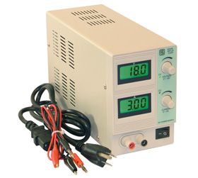
Or now that I know what the term "bench psu" means. I found this thingie...for twice as much :) (I only wish it was blaaack)

9600.jpg
 
Last edited:
Joined
Jun 7, 2009
Messages
118
Points
0
I think I understand now!!!!! just by looking at that bench PSU why these are such a great option.

I could wire permenent leads to my driver circuit with mated DC plugs attached, which means I can just plug the circuit into the PSU whenever needed *shrug*

I mean..this isn't exactly the direction I was planning on going and I might miss out a few "trial and error" learning experiences but for 60$ and a plug and play, tune and set PSU might as well do it right.


This discussion has been immensely helpful. Thank you all ^_^


Might I ALSO add a direct link to the flexmod user manual which I read last night (or was it early this morning..I cant remember). It does such a great job of establishing a procedural based tutorial. A real..tutorial, with like..all the bases covered and little knowledge assumed. for setting up the driver

http://hacylon.case.edu/laser/FlexModP3/FlexModP3_Manual.pdf

FlexModP3.jpg
 
Last edited:

Kevlar

0
Joined
Apr 26, 2010
Messages
1,353
Points
48
If you want to build a simple linear current driver, and use the 2.5A wall-wort you linked from Radio Shack, just use a LM350 instead of the LM317. The LM350 can output up to 3A where as the LM317 can only output up to 1.5A

For a simple tutorial on how to build the linear driver I like Rog88's. I think he is still a member here, just not very active. Here is a link to the tutorial on his site:

Laser driver - It can be done

If you want a labby driver, just put it in a project box, heatsink the LM350, and use a 25 Ohm pot, like this: 25 Ohm Rheostat 3 Watt Pot. Then you can put a knob on it to control the current up to 3A.

Just a suggesion ;)
 
Last edited:


Top