Welcome to Laser Pointer Forums - discuss green laser pointers, blue laser pointers, and all types of lasers

Buy Site Supporter Role (remove some ads) | LPF Donations

Links below open in new window

FrozenGate by Avery

I really dont understand drivers..

I actually do Think i would like to build one. Not only would it be satisfying but id have an excuse to make an enclosure for it.

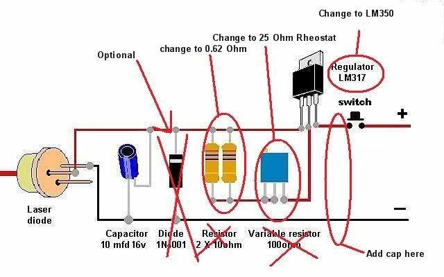
but I have no idea how to read that diagram for the LM350 which sounds like what I want :) , the instructions arent as clear as the one for the LM317 :(
 
Last edited:


^^^ The LM350 is wired just like the LM317. Just follow the diagram from the LM317 datasheet or the driver link I referenced above.

Sorry, I don't know about EMP. That stands for Electrical Magnetic Pulse? Did you mean ESD (Electrical Static Discharge)?
 
^^^ The LM350 is wired just like the LM317. Just follow the diagram from the LM317 datasheet or the driver link I referenced above.

Sorry, I don't know about EMP. That stands for Electrical Magnetic Pulse? Did you mean ESD (Electrical Static Discharge)?

So im going to head off to radio shack today and buy the parts needed to tinker with :)

So I just need as it says..


1 -mfd 16v capaciter

1-1n4001 diode

2 - 10 ohm resistors

1 - 100 ohm variable resistor

and a LM350 regulator instead of an LM317 regulator?

And a bread board for it all :)

I also need to pick up a new multi meter today. my 3$ harbor freight special got the electrodes melted recently =D.
 
Last edited:
Well wow..radio shack was surprisingly not helpful.

They had nothing that could be discribed as a "16 v capaciter"

Nor discribed as a "100 ohm variable resistor" They had a bunch of "potentiometers" but they were all like in the kiloohms range..or sub 100

And they only had an LM317T.

Only things I found were 2 10 ohm resistors, and the 1n4001 diodes and a bread board.

The guy didin't really know any more than I did :)


Oh also!

I wasn't sure what resistors to get...there were a couple 10 ohm resistors...1/4 watt...1/8 watt...

I got the 1 watt 10 ohm ones cuz they looked like the ones in the picture..and I figured since I might go for an output of 2 watts...that they should be able to handle a watt a piece.

Yeah, Radio Shack doesn't have much. I go there very little now. They don't even know what a resistor is!!! :rolleyes:

For most component parts order from mouser or digikey.

As far as the resistors, you'll have to use Ohm's Law to calculate what resistor value to use to get the current range (or set current) you want. You can also use Ohm's law to figure out what wattage rated resistors you'll need.

Here is a link for Ohm's law:

Ohm's Law

Here is a LM317/LM350 calculator, pretty handy.

LM317 Current Calculator - Electric Circuit
 
Last edited:
Kk..

I just want to be able to drive a 445 NM diode to <2A if need be...

Thanks again for your patience.

I did find a Java bread board simulator in Java... but it doesn't seem to have very many features....I cant find any tabs to add componants with an assigned value..

I wonder if there are good sims that are eluding me on google..If I can simulate trial and error, and see my results ...

*edit*

http://falstad.com/circuit/index.html

Very nice. The UI is not very friendly though :) .
 
Last edited:
Using THIS LM317/LM338/LM350 Current calculator I figured you could use this 0.62 Ohm 3W resistor from digikey to get a max current of ~2A.

Make sure you heatsink the LM350. Wire in the 25 Ohm rheostat pot from RatShack as per the driver tutorial. The 1N4001 diode is only to prevent damage to the laser diode if you hook up you power + and - backwards so if your using a walwart and your confident you won't hook it up backwards you can omit it.

If you choose to use the rectifier diode I would upgrade to a 1N54XX series, they can handle up to 3A. IIRC, the 1N4XX series can only handle up to 1A.

I would also wire in a capacitor on the input AND output.
 
Last edited:
So then youd have a capaciter wired before the lm350? is that what you mean by input? So Have the current move through the capaciter, and into the appropriate "in" pin for the lm350?

Then capaciter..before the load?
 
Last edited:
Keep in mind I am no expert but I do have built several drivers.

Here is how I would wire it:

LM317-6.jpg


Maybe bobhaha, Jacob32123, or anyone else that sees this thread can confirm this is correct.

What I would do is wire it up, and hook it up to a test load to ensure everything is correct.
 
Meh, good enough. You'll survive without a cap on the input.

The resistance you have there will allow for a max of 2A and a minimum of 50mA and the resistor needs to be at least 3W.
 
Meh, good enough. You'll survive without a cap on the input.

The resistance you have there will allow for a max of 2A and a minimum of 50mA and the resistor needs to be at least 3W.


Thanks for the confirmation Cyp!! :beer:


Back
Top