Re: I have my diode, now where do I plug in teh ba
ant: These GB diodes are the closest thing we have to a known quantity, and people are getting a pretty good feel for what they can do and what kind of abuse they will take. Unless the cost of getting more diodes is negligible for you (not to mention the wait!) I would definitely err on the side of caution.
The capacitor is sort of a "store and forward" device for voltage. It takes in the voltage on one side, and passes it out the other, storing a small amount in the dielectric between the two charged plates. By placing it across the diodes, you are giving the voltage spikes a nice safe place to go, instead of through your LD.
You are right that there is a chance of discharging a lot of volts if the capacitor is disconnected. This is why it's advised to solder the cap directly across the LD's pins immediately. Be sure to do this while it's discharged, and also add any other components at the same time so you don't disconnect the cap while soldering other bits.
Another good item to attach directly across the LD's pins is a standard silicon diode (anything 1N400X should do, i got a pack of 1N4001's for like 2 bucks at radio shack). Install this diode "backwards" across the laser diode (the side of the 1N400X diode with the grey stripe (negative) should go to the LD's positive pin. This addition keeps current from ever flowing backwards into the laser diode by providing a low resistance path for reverse current, avoiding the LD.
The voltage regulator (which is being used as a current regulator) is somewhat optional, the main reason for including it is that, as the LD heats up, its internal resistance goes down, which will cause current to start creeping up. Having the LM317T in series will pinch off the voltage as needed to keep the current nice and steady. If you end up mounting your laser in a 1W LED flashlight (like the Dorcy Mini) it already has some sort of current regulation built in, so you just need to worry about the capacitor, diode, and an inline resistor to fine-tune the current to exactly what you want.
A couple other things: While you can certainly calculate the amperage of your circuit as V/R, a simpler way would be to measure it directly. Set your Multimeter to the 10a scale (making sure the positive probe is moved to the 10a slot). Disconnect your power source, and disconnect the LD's positive pin from the circuit. Use the two probes on your multimeter to bridge the LD's positive pin back to where it was plugged in. I would strongly suggest using aligator clips for this. Your multimeter is now inline to the circuit and will measure the amps flowing into your LD in real-time. Reconnect the battery source and you're good to go.
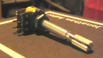
As Death Angel said, the best thing you can do is set up your amp meter, get a 25 ohm potentiometer, put it in series with another tiny resistor (1-10 ohms) as a safety net (so R can't reach 0 when you crank the pot all the way down). Then you can just fine tune the amperage to whatever suits your needs. Once you've got it how you like it, measure the ohms across the potentiometer and replace it with a standard resistor of the same value.
Really, I can't stress enough how important these extra components are for the life of your diode. Whoever put out the howto on running a LD in a mini-mag flashlight with no protective circuitry really did a disservice to all the hobbyists out there getting started, and probably has caused a lot of grief and dead diodes.
Hope this helps. I almost went the gung-ho route myself until I realized just how much diode life you'd be sacrificing (and always the possibility of insta-frying it). I just realized I repeated half of Daedal's driver thread. Thanks Daedal
")
Hope it was useful anyway.
-burnsy


")
")