Welcome to Laser Pointer Forums - discuss green laser pointers, blue laser pointers, and all types of lasers

LPF Donation via Stripe | LPF Donation - Other Methods

Links below open in new window

ArcticMyst Security by Avery

I built a 1w 525nm and the s4x host I got from Surivual lasers, and the tailcap system isnt working

-UnkownOne

Member
Joined
Mar 11, 2019
Messages
43
Points
8
Hello, I was building the laser and everything put together but the laser won't turn on when I took apart the tail cap and the ring and button, the s4x host, took out the tailcap board and copper ring and tried it like that and it worked, for some reason the ring isint making contact with the whole tailcap or something, it definitely works, but only when I take it apart and try it without the cap it works, is there any way to fix this?
Thanks, Artsem


Joined
Dec 15, 2014
Messages
6,782
Points
113
H if you screw the thin ring off that holds the switch down you should see the copper on the outer edge of the contact board
Just. Small amount of solder on that edge then screw the retaining ring back on tight
 

-UnkownOne

Member
Joined
Mar 11, 2019
Messages
43
Points
8
H if you screw the thin ring off that holds the switch down you should see the copper on the outer edge of the contact board
Just. Small amount of solder on that edge then screw the retaining ring back on tight
alright thanks, I'm almost home gonna go and try that and see if it works, so solder the copper of the board on the edges to the ring got it, I tried do it on top of the ring to center of board didn't wanna hold even with flux lol, hopefully this works
 

-UnkownOne

Member
Joined
Mar 11, 2019
Messages
43
Points
8
H if you screw the thin ring off that holds the switch down you should see the copper on the outer edge of the contact board
Just. Small amount of solder on that edge then screw the retaining ring back on tight
I'm looking and see only 2 wired of metal on the edge of the board and solder to board to the clicker, where do I put older on, then do I just close it, and it fits or what, sorry if I'm not understanding, my first build!
 
Joined
Dec 15, 2014
Messages
6,782
Points
113
Hi,
Solder on the outer edge only the threaded ring is only to keep the switch in contact with the host,

Rich:)
 

-UnkownOne

Member
Joined
Mar 11, 2019
Messages
43
Points
8
Tell me if I'm getting this right so solder a small piece on the outer edge of the tailcap board, like the chip and it should contact the outer walls which will make it turn off and on? or do I solder something to the outer board?
 
Joined
Dec 15, 2014
Messages
6,782
Points
113
Hi, The ring needs to make contact with the with board for grounding.

Rich:)
 

-UnkownOne

Member
Joined
Mar 11, 2019
Messages
43
Points
8
I solder the edge of the board and nothing happened while I was trying to solder the ring to the board will it just won't connect to each other, so if it's loose it won't work, it has to be solder to the board?
 
Joined
Dec 15, 2014
Messages
6,782
Points
113
Hi, Yes I stated solder to to board were the CU is shown on the outer rim. the Al ring is just to hold the switch in place and make good Neg contact. Survival lasers is a very good company and a member here at LPF. if you don't get it working I think they have spares on the site. Or Email Garry he is a great and understanding gentleman . I repaired a few of those switches and they are great switches and an awesome host.

Rich:)
 

Garoq

0
Joined
Aug 27, 2010
Messages
1,525
Points
83
100% of the tail caps are tested for proper operation before shipment. Try some battery spacers to make sure the battery contacts are firmly touching the driver and the spring. We will send a replacement if that doesn’t work. :)
 
  • Like
Reactions: DTR
Joined
Dec 15, 2014
Messages
6,782
Points
113
Hi Gary,
Thank you for coming through for this member, great to have you on board here at LPF.

Rich..
 

DTR

0
Joined
Jun 24, 2010
Messages
5,684
Points
113
I solder the edge of the board and nothing happened while I was trying to solder the ring to the board will it just won't connect to each other, so if it's loose it won't work, it has to be solder to the board?

If you think it might be the contact board is not making good ground contact via the ring which you can test several ways either via a dmm with a continuity test from the metal body of thee host and the negative wire going to the driver or if you don't have one you can always get creative and find something which you can use that path to complete a circuit.

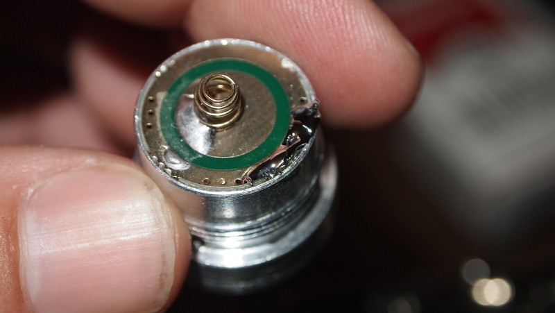
If you think it is not getting a solid connection here is the method found to be the least problematic. If you see some of my build threads where using flashlight bodies at the host with that type of pill that seats a round driver or in this case a contact boar that is pressed in some with a brass ring I had originally on the earlier ones used the common suggestion of the solder blob to the brass ring or edge but I found that can be frustrating at times since soldering to brass could have issues if the solder and the brass or aluminum did not both get up to the proper temp to make a proper bonding. If you end up with a cold solder joint it can just break loose with any contortion like expansion/contraction from temp changes.

This one is an example of that method.
p1011871.jpg


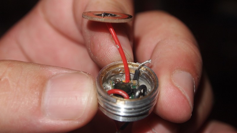
Eventually I came up with going to the pinch technique. Where would run the negative wire directly between the edge of the board and the pill and then press the contact board in pinching the wire making a solid connection.

LIke this.
65191
For the negative wire you just pinch it between the pill and the ring that presses in and use a pair of pliers or a vice to press it in.
65192


Here is another example in this build thread.
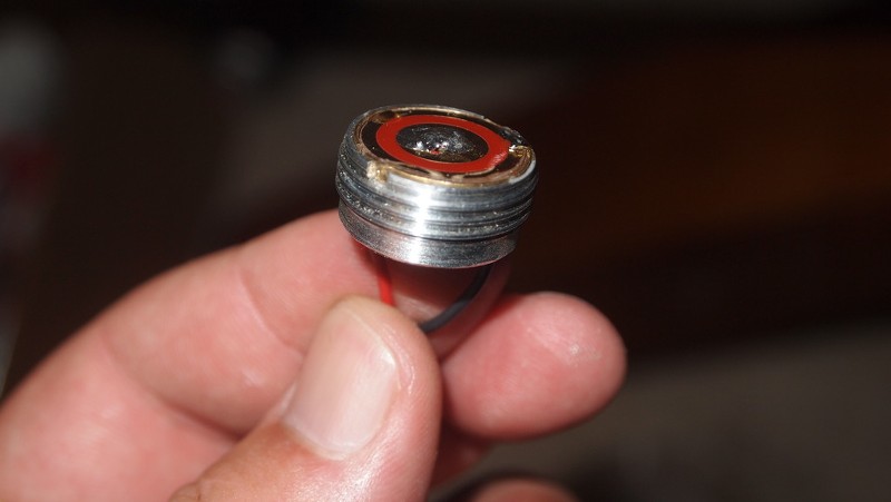
Next I strip the negative lead as it will be sandwiched between the contact board and the pill.

2zq4.jpg


Then I press the driver board in and put a little thermal adhesive to seal the compartment.

YaiXvh.jpg


I don't show it there but I also added to that by tinning the exposed wire to give it more strength from stress from pulling or twisting the lead also it is easier to make sure you don't have any stray strands floating about.🍺


If that is good and the circuit is being broken somewhere else as Gary mentioned a few common issues like when using multiple Li-ions in series some have a recessed positive tab which you might need to get some of the little 2mm-3mm neodymium magnet discs to use a spacer. Another issue I have seen is some of the cells with protection can be much longer than normal. With a lot of tailcaps if there is too much pressure from the batteries and you have to screw down real hard it can actually contort the clicky enough to break the contacts that are supposed to be touching when the clicky is in the engaged position. Sometimes keeping the clicky from being pushed. You can try and unscrew the tailcap some and see if it comes on to rule that out.

Last think I have seen quite a bit when I was offering hosts which I had done a few times and had many customers do. If theres is a short in say the pill the clicky can melt internally and go bad. Usually seizing up but not always.

🍺
 

-UnkownOne

Member
Joined
Mar 11, 2019
Messages
43
Points
8
No, the driver side is working fine since my batteries are the flat top I made a bump with solder to make sure it contact if you put the batteries in 2x16850 and you bridge the end to the host with a piece of metal it turns on and focuses, the switch also works when you take it out of the tailcap and with the ring make contact to the battery and host switch turns it on and off but when whole tailcap is assembled it just won't work?
 

-UnkownOne

Member
Joined
Mar 11, 2019
Messages
43
Points
8
Yea, I really tried soldering the brass ring to the board but no matter what I tried I even tried using solder flux which helps solder stick, the bridge connection, just won't hold, got so frustrated honestly. Hopefully, this gets fixed, the batteries are also making contact because when I try to shake the host there is no sound from batteries plus I tried looking and it looks like they touch, will try with magnet though.


Top