Welcome to Laser Pointer Forums - discuss green laser pointers, blue laser pointers, and all types of lasers

LPF Donation via Stripe | LPF Donation - Other Methods

Links below open in new window

ArcticMyst Security by Avery

Hyperion LPM + Vritonuzz Data Logger Platform

Joined
Mar 27, 2011
Messages
504
Points
43
I will continually updating this thread. :D

Hi folks, pardon my english. :D

Proudly present to you all:
Hyperion Laser Power Meter platform. 👼

*This is NOT a sale thread*
For the sale thread, please go to >here<

Background:

This all started back in 2010 when i'm still on my first year in electrical enginering college, i have my first 532nm 200mW laser from rayfoss after saving up for uncountable month.
It was a good times back then when the quality of material is still on a top notch and of course the price is still high, and one thing missing is an affordable LPM :cryyy:
As you could imagine for a new hobbyist or budget hobbyist or those who only have a few laser and most of it is just a pen laser, getting an LPM is just.. too much :cryyy::cryyy::cryyy::cryyy:
That time i had only those 3.2W OEM LPM you-know-what, and as per my view is a very expensive LPM even though that is supposed to be a hobbyist.
I also remember the radiant alpha $99 is always sold out at that time :cryyy::cryyy::cryyy::cryyy:

After several years, i come to realization that building an LPM is easy, or at least i have a big picture of what to do.
After researching, trial and error, thesis request, and having a bunch of project related to this LPM, i decided to make one cheap platform for all.
The goal is to create a cheap platform so that a new hobbyist and budget hobbyist can afford having an LPM.


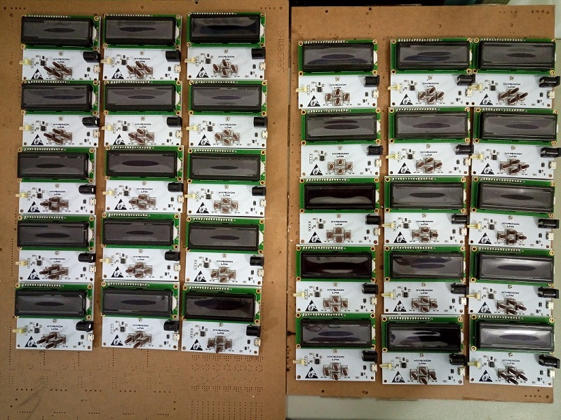
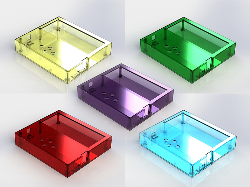
Here is the pictures:

Set-LPM-1.jpg


freshlysoldered.jpg


MainForm.png


Enclosure-All.jpg


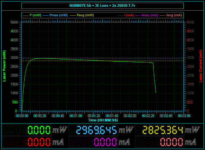
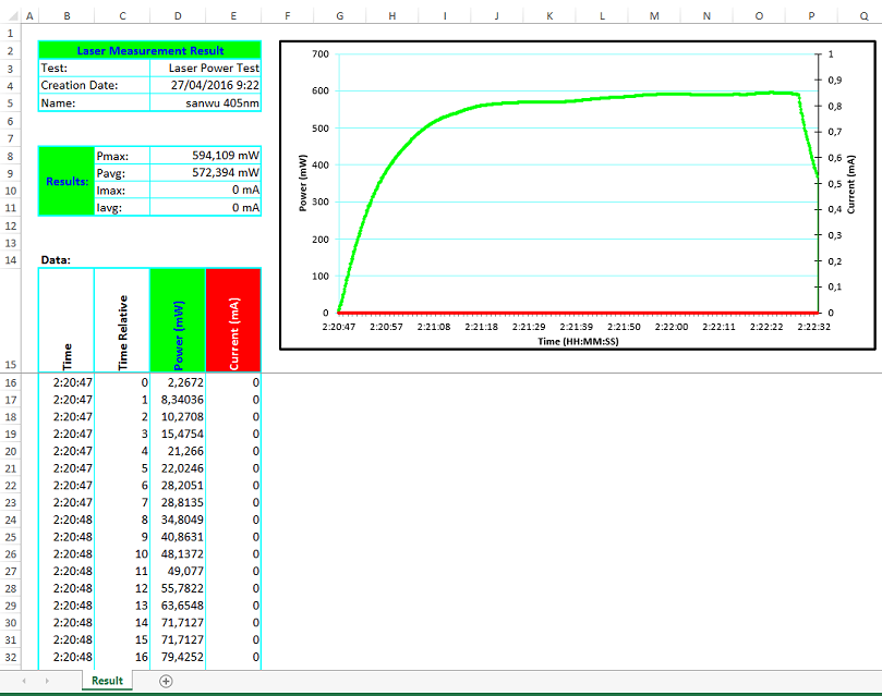
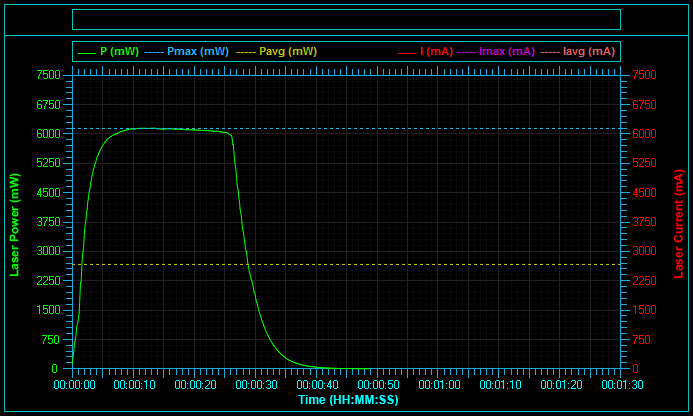
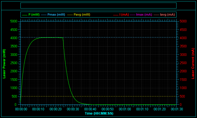
Sensor response time (default sensor 6x6mm):

Speedtest_6_W.png


Speedtest_4_W.png


Thermal_Test_3_6_W.png


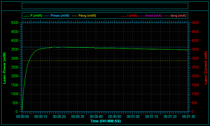
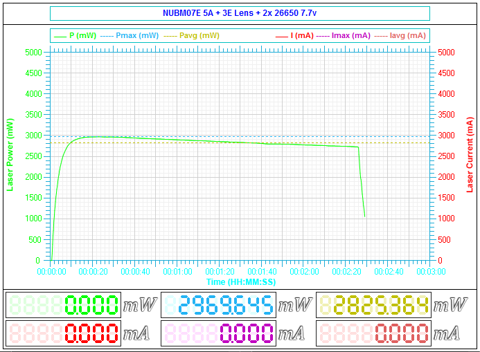
And here is the slower sensor (8x8mm or 10x10mm) response time for comparison:
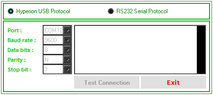
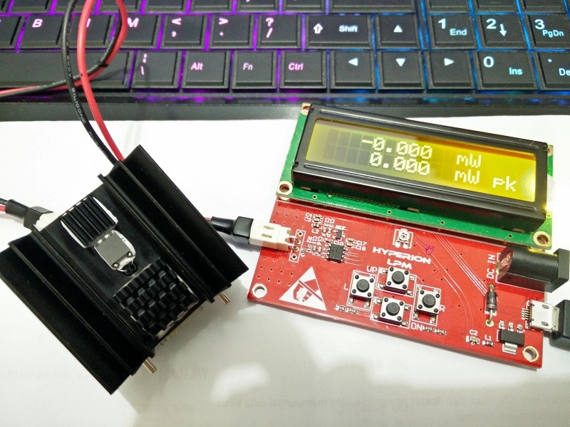
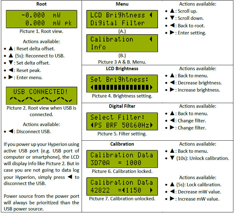
Slow_speedtest.png


Hardware interface:

Interface.png


Taking_care.png


Technical specification:
  • Max measurable power:
    • Hyperion Ag: 6W or 15W*
    • Hyperion Cu: Using equal sensor like the Hyperion Ag, but limited to 2000 mW max.
  • Resolution: 1 uW**
  • ADC resolution: 22-bit, yielding 1.192 uV/bit with 2500mV Vref
  • ADC vref: 2500 mV or 4096 mV depending on stock.
  • Uncertainty:
    • Laser power 0 mW to 4500 mW (0 mW to 15 W for uncoated sensor): ±5%***
    • Laser power 4500 mW to 6000 mW (15 W to 20 W for uncoated sensor): ±5% + (-10%)***
  • Sensor area:
    1. 36 mm² high speed sensor (default)
    2. 100mm² slow sensor.
  • Options for sensor coating:
    1. HPCVD micro carbon deposition over high temp resistant matte black paint (for detecting low power laser).
    2. High power + high damage threshold carbon coating at least 480W/cm² (default) , tested by focusing 3.6W multi mode laser into 0.5x1.5mm spot size. Results: no damage, smoke, or trace at all.
    3. No coating at all, yielding broadband rejector instead of broadband absorber with the highest damage threshold among the three (damage threshold of alumina ceramic Al²O³). Therefore producing higher measurable power albeit at worse resolution (13 uW).
  • Sensor response time 0-90%: ~4-6 sec****
  • Sensor response time 0-100%: ~10-12 sec****
  • Display:
    • Hyperion Ag: High contrast LCD.
    • Hyperion Cu: Standard LCD.
  • Hardware interface:
    • Delta-reading (software zeroing).
    • Peak detector.
    • Brightness.
    • Digital filter.
    • Easy re-calibration (only for HyAg).
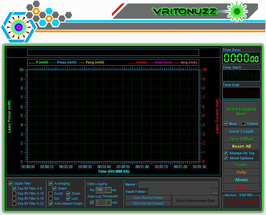
  • Vritonuzz data logging software (download v1.3.0.162 here):
    • Freeware for all, support various protocol.
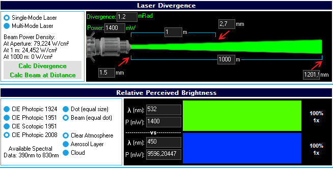
    • Tools including divergence calculator, relative perceived brightness calculator.
    • Intuitive interface.
    • Configurable x-axis graph with zoomed or scrolling.
    • Auto-scale graph.
    • Various digital filter.
    • Smart averaging.
    • Delta-reading (software zeroing).
    • Peak detector.
    • Configurable logging time.
    • Auto-logging trigger by power.
    • Delayed logging (5 sec).
    • One-click snipping graph.
    • Export data to spreadsheet format (.xls) and already nicely formatted too.
    • Plug n play without unnecessary effort like selecting COM or installing driver.
  • The board can be calibrated to read from ophir sensor directly, making this board a functional data logger board.

Absolute maximum rating:
  • DC-IN: 15V
  • USB Voltage: 5.3V
  • Measured laser: 6000mW for 6x6mm sensor (coated). 15W for 6x6mm sensor (uncoated). Please see below
Exceeding this limit may cause permanent damage to the device.

Calibration:

  • The sensor has been calibrated using consistent dual reference sensor that has been factory calibrated with alexandrite laser 755nm, it may also be calibrated using standard thermopile disk which NIST calibrated at 808nm.
  • Calibration transfer from reference to the Hyperion sensor done using 445nm, 405nm, or 808nm laser, producing roughly about <5% uncertainty.
  • If the uncertainty from the reference sensor (<4% from actual NIST value) taken into account, the max uncertainty will be <9.2% from the actual NIST value.
  • Reading above 4500 mW (or 15W for uncoated sensor) might skew to -10% due to the sensor's Vout saturation.

Here is some more information for people measuring their visible wavelength laser using 1064nm calibrated sensor:
  • Fact: Even if the sensor is NIST calibrated, doesn't mean that it will 100% accurate when measuring laser with different wavelength compared to the laser used to calibrated that sensor at NIST.
  • Reason: Because there is no single coating in this world capable of true "flat" broadband response. Even for those ophir head, you won't find the specific spectral response chart because they don't want you to know (unless i'm missing something). AFAIK from their youtube, this type of coating absorbs more at wavelength below 800nm, meaning if it's NIST calibrated on YAG 1064nm with 100mW power reference, it won't give you 100mW when measuring true 100mW 447nm. Instead it'll give you readings above 100mW because of more absorption. The workaround for their product is, they are compensating the reading and user can select if want to measure <800nm or >800nm (this choice exist on their power meter interface, AFAIK). This is also the reason why some OEM design may want you to chose in which wavelength do you need your sensor to be calibrated to.
  • Conclusion: Your sensor will give fairly different reading from its guaranteed calibration, if you are measuring wavelength other than 1064nm, especially if your laser's wavelength is below 800nm (Ophir 20C-A-1-Y is calibrated with "Y" = YAG laser = 1064nm). This is also the reason why i calibrated the Hyperion sensor using sensor that has been calibrated using wavelength below 800nm.

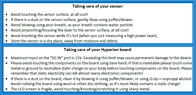
Precaution about non warranted sensor:
  • The default sensor is a 6x6mm peltier. It can be bought here. As you can see those sensor are rated for 200°C.
  • A normal operation (e.g when reading 3600 mW laser) can cause the sensor to heat up to >300°C which is above the Tmax of those peltier and can melt the solder joint of the PN junction. That's why you need to avoid knocking the sensor while it's hot.
  • Under normal commercial warranty, operating above maximum rating will void the warranty. That's why even our "normal" operation will void the warranty from the peltier's manufacturer.
  • While focusing the laser to the surface of Hyperion sensor doesn't degrade the coating, it will stress out the particular PN junction behind the ceramic where your laser is being pinpointed. This might cause a temporary or permanent failure to the sensor.
  • It is better if you point your laser at different surface area of the sensor on each measurement to prevent stressing the PN junction.
  • Measuring high power laser continuously can cause thermal runaway on the sensor due to the nature of semiconductor (it'll die and cant measure anything anymore). Most semiconductor device/IC has thermal shutdown feature that will shutdown the device/IC when it's reach 150°C, yet our normal operating temperature reach two fold of that and it doesn't have that feature. In conclusion, the recommended max is 30 secs when measuring above 4W laser (12W for uncoated sensor), and it's better if you used forced air to cool the heatsink of the sensor, set the fan to blow facing the back of the sensor.
  • Furthermore, the sensors itself (the coated sensor) are not strong enough to be heated by laser with power more than 6W (15W) (even though the coating is strong enough for it). All commercial thermal sensors capable of measuring high power lasers are using metal to detect the heat which is not a problem for it, on the other hand, this sensor is a tiny semiconductor that is breakable by heat.

Price when it's fully assembled: US$75* for Hyperion Cuprum, and US$150* for Hyperion Argentum.
Hyperion Cuprum can be upgraded to Hyperion Argentum, you only need to pay the rest, and you'll get activation code to unlock the limit and easy-calibration feature :D


These policies are made for the sake of low budget hobbyist or new hobbyist so that they can afford it, and just in case they need more than 2000 mW, they can just upgrade it without buying a new one.

FYI:
EMS Destination From Indonesia

Contact:
email.png


*Depends on the sensor and coating. Linearity tested up to 4.5W with coated sensor or 12W for uncoated sensor, above this level the reading might skew to lower value (about 10%) due to sensor's Vout saturation.
**Depends on the sensor, coating, and digital filter.
***Approx. value from the reference sensor only, not including the uncertainty of the reference sensor towards NIST.
****Using default sensor. Cheaper & slower sensor are available upon request.
 
Last edited:


Joined
Mar 27, 2011
Messages
504
Points
43
Re: Hyperion LPM Platform

The Vritonuzz data logging interface is a freeware for all of you, it can datalog almost everything, provided that i know the data format sent by device which need to be logged :whistle:

Let the screenshot do the talking:

Vritonuzz datalogging interface:
MainForm.png


Tools, including divergence calculator and relative perceived brightness calculator
RPL-1400.png


Port config
Port-Config.png


Graph Black:
NUBM07-E-5-A-3-E-Lens-2x-26650-7-7v.png


Graph White:
NUBM07-E-5-A-3-E-Lens-2x-26650-7-7v-white.png


Exported spreadsheet format
Spreadsheet.png


>Download Vritonuzz v.1.3.0.162<

Platform: Windows
License: Freeware "as is"

Currently it can datalog:
  • Hyperion LPM
  • LPM using "Open LPM" or "Simple LPM" Protocol
  • LPM using "Laserbee" protocol


.
 
Last edited:

SIEVA

0
Joined
Apr 13, 2016
Messages
21
Points
0
Re: Hyperion LPM Platform

This is very cool!

I was just looking at what these things cost, and oh man, it's gonna take me a long time to get one of those. With your design, there suddenly seem to be some light over the horizon.

Questions:

a) Why does it take to long for the measurement to finish. I.e. the counting?

The only explanation I can think of, is that you're measuring the MAX temperature (for your sensor+heat conductor) and then trying to find the stable state of that measurement.

A quicker solution may be to plot how the first and/or second derivative of the temperature (change) look for different powers and use that to get a more instant result.

b) What micro-controller are you using?
c) Where can I get a sensor to experiment with?

Good Luck!
 
Last edited:
Joined
Mar 27, 2011
Messages
504
Points
43
Re: Hyperion LPM Platform

This is very cool!

I was just looking at what these things cost, and oh man, it's gonna take me a long time to get one of those. With your design, there suddenly seem to be some light over the horizon.

Questions:

a) Why does it take to long for the measurement to finish. I.e. the counting?

The only explanation I can think of, is that you're measuring the MAX temperature (for your sensor+heat conductor) and then trying to find the stable state of that measurement.

A quicker solution may be to plot how the first and/or second derivative of the temperature (change) look for different powers and use that to get a more instant result.

b) What micro-controller are you using?
c) Where can I get a sensor to experiment with?

Good Luck!

I'll post a sale thread for this LPM, once the custom sensor is arrived to me from its manufacturer.

Right now i don't have an open source design for LPM, because i'm using 8-bit microcontroller that AFAIK doesn't have cheap development board out there like arduino. Also the programmer for this particular MCU is rather expensive.

FYI: I release the datalogger software as a freeware, but since i don't know the other communication protocol (yet), the other user that uses other LPM might just use this program to re-plot their graph or convert from .csv to .xls, for now.

a.) Pardon my english, but i don't quite understand your question, are you refering to the response time (Power 0-90%: 10-15 sec)?? About that, you can search on this forum about "LPM response time". Tl;dr (simplest explanation): It's the time needed for one side of the sensor to reach thermal equilibrium with the power of incident light. As the light "hit" the sensor, almost all of the light's energy/power is converted to heat, while the rest is got reflected. There is more than that, you need to recheck with some scientific article, papers, or journals too.

b.) It's just 8-bit MCU (explained above)

c.) If you want to create your own LPM, you need to carefully select the sensor that small enough and cheap enough to use. You might want to open this link: TE Technology or Custom Thermoelectric
 
Last edited:
Joined
Sep 20, 2013
Messages
17,402
Points
113
Re: Hyperion LPM Platform

This is very nice. I wonder if I can use this to data log on my Scientech S310. I use it with an AC2500 astral calorimeter. It has an RS-232 interface and I can change the baud rate from 300 to 19,200. This meter measures from 0.01mW to 10 watts with an accuracy of 3% and an efficiency of better than 1%.

Edit: + REP
 
Last edited:

SIEVA

0
Joined
Apr 13, 2016
Messages
21
Points
0
Re: Hyperion LPM Platform

Right now i don't have an open source design for LPM, because i'm using 8-bit microcontroller that AFAIK doesn't have cheap development board out there like arduino. Also the programmer for this particular MCU is rather expensive.

Oh, but I wasn't expecting you to spill your design. I was just curious how it works. Too bad the MCU programmer is expensive, when there are so many other cheap alternatives. Did you develop the firmware yourself? (If yes, then you can always attempt to port to a cheaper device.)

a.) Pardon my english, but i don't quite understand your question, are you refering to the response time (Power 0-90%: 10-15 sec)?? About that, you can search on this forum about "LPM response time". Tl;dr (simplest explanation): It's the time needed for one side of the sensor to reach thermal equilibrium with the power of incident light. As the light "hit" the sensor, almost all of the light's energy/power is converted to heat, while the rest is got reflected. There is more than that, you need to recheck with some scientific article, papers, or journals too.

Ahh, thanks. Now I know what is an LPM, but I'm still not sure what they use as sensors. Are they using TEC? (Since you linked to that.)

But I also understood how the measurements are taken, so if you wrote the measurement software yourself, you could try to add calculating the rate of change and use that to extrapolate (much quicker) where the thermal equilibrium will take place. Thus giving you a fast, but approximate reading, until you get the final true reading.
 
Joined
Mar 27, 2011
Messages
504
Points
43
Re: Hyperion LPM Platform

This is very nice. I wonder if I can use this to data log on my Scientech S310. I use it with an AC2500 astral calorimeter. It has an RS-232 interface and I can change the baud rate from 300 to 19,200. This meter measures from 0.01mW to 10 watts with an accuracy of 3% and an efficiency of better than 1%.

Edit: + REP

That a nice meter you got there.
It's doable as long as the data sent is not encrypted and can be interpreted by looking at the data itself using naked eye.

The Vritonuzz datalogger will continuously updated and developed (provided that i still have time to do it), and since long i decided to make it able to read/write data to other LPM. You can wait until i add the serial interface version, as right now im just using HID plug n play protocol. :beer:

Oh, but I wasn't expecting you to spill your design. I was just curious how it works. Too bad the MCU programmer is expensive, when there are so many other cheap alternatives. Did you develop the firmware yourself? (If yes, then you can always attempt to port to a cheaper device.)

Ahh, thanks. Now I know what is an LPM, but I'm still not sure what they use as sensors. Are they using TEC? (Since you linked to that.)

But I also understood how the measurements are taken, so if you wrote the measurement software yourself, you could try to add calculating the rate of change and use that to extrapolate (much quicker) where the thermal equilibrium will take place. Thus giving you a fast, but approximate reading, until you get the final true reading.

Don't worry, actually i decided to give tips n trick or design as much as i could in this forum anyway. About that programmer, actually there is a cheaper version of it, but since i have a bad experience using it, then the only safe option is using its legitimate programmer/downloader. You could imagine about 100++ MCU got corrupted because of it :cryyy:

Many DIY LPM are using TEC, while branded LPM using either thermocouple disc, photodiode, or pyroelectric sensor.

i actually did using that algorithm only to determine the average (smart average). So when the data gradient reach some value, it will start counting the average instead counting from the start. But sometimes you need to count the average from start too.
I think that using extrapolate means that the data will have false reading or it just means falsifying the data, what do you think? While some branded meter out there has an analog "speed up circuit" i don't think we can add that method on the digital part.
All i can do to shorten the transient is by choosing the right TEC.

Oh im def in. How many mw with upgrade?

That still TBD. The sensor is still being manufactured in China.
The upgraded version of Hyperion Cuprum is actually a Hyperion Argentum and will have the same max reading just like it.

The estimate output based on the TEC that is available right now on me is:
Sensor output = ~140 mV/W
Max theoritical per ADC specification is (ADC vref)/(Sensor output) (W)
So if using 2500 mV Vref, the theoritical max power is: 2500/140 = 17.85 W


But that's not entirely possible because of heatsink factor and the max amount of voltage that can be generated from the TEC itself.
Therefore it will be just like those Ophir head, you can measure with ambient cooled e.g up to 5 W, and need air cooled or attach/add more heatsink to measure beyond that.
 
Joined
Sep 20, 2013
Messages
17,402
Points
113
Re: Hyperion LPM Platform

I'm pretty sure it's just data. I look forward to seeing your completed version. Thanks.
 

Benm

0
Joined
Aug 16, 2007
Messages
7,896
Points
113
Re: Hyperion LPM Platform

This looks like an interesting meter!

The pricing also seems pretty good, although i don't really like the idea of having to pay extra to unlock a feature that is only in software. I know it happens in more products, but i still find it kinda shitty.

If there would be a difference in something like the sensor size it would by all means be reasonable though, and you did mention various sensor sizes - any more info on that?

Btw, just curious, where in indonesia are you based/shipping from?
 
Joined
Mar 27, 2011
Messages
504
Points
43
Re: Hyperion LPM Platform

I'm pretty sure it's just data. I look forward to seeing your completed version. Thanks.

:beer::beer::beer::beer::beer:

This looks like an interesting meter!

The pricing also seems pretty good, although i don't really like the idea of having to pay extra to unlock a feature that is only in software. I know it happens in more products, but i still find it kinda shitty.

If there would be a difference in something like the sensor size it would by all means be reasonable though, and you did mention various sensor sizes - any more info on that?

Btw, just curious, where in indonesia are you based/shipping from?

Actually in fact it's quite the opposite, i was just designing for the USD$150 price, but then i remember even with $150 power meter, some may not have that much money to buy it. Then instead of creating a whole new board (i did it actually, with smaller board and 8x2 LCD) i decided to make it just like a "trial" product in hope that a low budget hobbyist can afford, as for me of course i hope that they upgrade it someday :D

This way, at the end the low budget hobbyist will have $150 power meter just like they pay it twice, and they can have it for just USD$75 on the first payment while the rest they can save up again in some period.
Various sensor size means various price too, that's why it is still TBD. The default is the 8x8mm though.

And here is the bad news:

The (China) suppliers for the 8x8mm sensor is gone by now, they doesn't even reply to any of my message. So that's why there are other options for the sensor size.
I can't import from US because i'm afraid i can't keep the price as low as this.
Right now the alternative that i think the most effective is 6x6mm that is being produced in china and they tell me that it will be finished by this week.

BTW i'm shipping from Jakarta, ID should you want to check the shipping cost.

Here is the link to the equivalent product with equal or nearest dimension:
6.2x6.2mm
8x8mm
10x10mm
 

Benm

0
Joined
Aug 16, 2007
Messages
7,896
Points
113
Too bad about the supply problems - i wonder how much power a 6x6 mm sensor could handle.

I guess the idea of offering an early version with 2 watt limitation at reduced price is reasonable as you are still trying to figure out the maximum power to be measured after further testing.

For more power a bigger sensor and/or heatsink could be useful. If that turns out to be the case you could still sell a combined hardware and firmware update package to lift the first series to the full capability of the final one. I'm not really sure if that is possible if they are individually calibrated - also depends on how you update the firmware, can it be done over usb, jtag or something?
 
Joined
Mar 27, 2011
Messages
504
Points
43
pardon my last post if it contains ambiguity, here i straighten it out more:

At first the design was just for one product called Hyperion Argentum, but with considerations above, i decided to bring down the price thus making lower version of Hyperion Argentum called Hyperion Cuprum with the same hardware as Hyperion Argentum, and it's not an early version. User may be able to choose their own sensor type for lower price or shorter response time.

I need to build up and sort all the things, then i'll update the thread and add some comparison to give clear information.

The TBD still exist because right now i still have a diverse combination for which heatsink to be used in which sensor. It might just like the photo, or i'll add more aluminum block with more small finned heatsink, the goal is to have small enough heatsink but as low as possible thermal resistance @ natural and as big as possible heat dissipation with as low as possible temperature rise.

The firmware is fixed, therefore there would be no upgrade at all. It's impossible right now to add more code as i already used up all program space on the MCU :banghead:
User can easily change calibration data should they have another analog sensor.
 
Joined
Sep 20, 2013
Messages
17,402
Points
113
That's great as my Scientech has an analog output as well. It doesn't change, however, when you change the scale you are using. It is locked into a 3 volt full scale output for every scale.
 

Benm

0
Joined
Aug 16, 2007
Messages
7,896
Points
113
Ran out of space on the MCU? Guess there usually is a model with more memory etc with the same pinout, albeit more expensive.

In any case i'm mostly curious about the sensor assembly. As long as that's solid there always is the option to combine it with better adcs, more powerful processors and what not in the future.


Top